
5 Days- That's a Lightning Fast Turnaround Time!
1
Upload Files and Pay
Upload PDF or CAD files, and pay to start the process. An engineer is auto-assigned to your project.
2
Document Review
An engineer will review all the documents shared and connect with you if anything else is required. Initial work starts.
3
Work Starts
Actual design/ report creation work begins.
4
Quality Check
The design and report are checked by the project manager to make sure 100% quality work is delivered.
5
Delivery
The design/ report is delivered to you.
Get Your Riser Diagram In 3 Easy Steps
Documents Required
Architectural plans and elevations in CAD & PDF, HVAC & plumbing equipment list/photos with model numbers along with kitchen equipment photos/cutsheets.
Delivery Time & Standards
We deliver your drawings (digitally) within 5 business days as per Local/IBC standards.
What's not Covered
This service does not cover site visits, stamping, DOB/DEP filing, and more than 2 minor iterations.
Service Constraint
The service fee is limited to per building up to 6 floors.
$1000*
Riser Diagram


Get your CAD riser diagram at lightning speed.

Avoid redrawing the design.

CAD design with no errors.

Riser diagrams are available for all building types.
MEP Riser Diagram: Mechanical, Electrical, and Plumbing


Reliable
Our experienced designers are trusted by countless businesses and clients for their excellent work!
Easy
Just hand over your sketch or CAD files- we will take care of the rest.
Fast
We deliver right on time so that you can build faster and enjoy a quick value for money.


Our on-demand engineering expert
Still not sure about how to proceed?
YOU CAN WRITE TO ME AT inquiry@ny-engineers.com
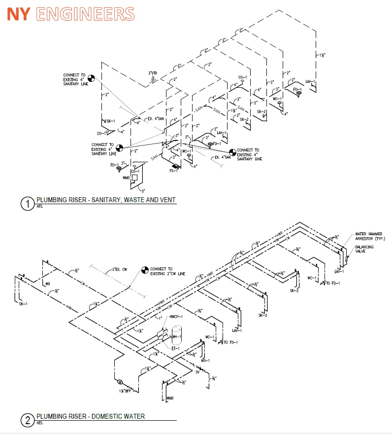
Riser diagrams provide a clear and simple representation of building system layouts, which are not always evident in construction drawings and 3D building models. They are especially useful when architects and engineers must discuss a building project with contractors, subcontractors and equipment providers. Construction drawings by themselves can be confusing for someone who was not involved in the design stage - understanding them is much easier after reviewing the riser diagrams.
Once a building is operational, riser diagrams are also useful for maintenance personnel. Troubleshooting becomes simpler when they have a clear picture of the MEP layouts, and they can easily pinpoint the location of key equipment. Riser diagrams are also helpful when planning a building renovation or expansion, since design engineers have a clear starting point.
BIM software can generate riser diagrams automatically from building models, and they are also updated automatically when design changes are introduced. NY Engineers has a track record of over 1000 projects, and our design services include BIM-based riser diagrams for any application: HVAC, electrical, plumbing, gas piping, fire sprinklers, fire alarms, solar PV, etc.
Riser diagrams are useful for anyone working with buildings, at any stage of their service life: design, construction, operation and maintenance, major renovations or energy retrofits.
- The layout of MEP installations is not evident in construction drawings, especially when there are long raceway/conduit/piping runs or vertical distances involved.
- Riser diagrams condense an entire MEP system in a single page. They provide key information about components and their interactions, but without showing the complex geometry of the actual installation.
Riser diagrams are not only technical documents, but also valuable communication tools. Thanks to their user-friendly format, riser diagrams also simplify communication among the parties involved in construction projects: owners, architects, civil and structural engineers, MEP engineers, general contractors, specialty subcontractors, equipment providers, etc.
1) Construction Managers
Using riser diagrams as reference, construction managers can coordinate the work performed by trade contractors more effectively. Construction drawings don’t always show the interactions between MEP components, and scheduling an installation based only on drawings can be a challenge. Riser diagrams give construction managers a clear overview of the project, helping them prevent expensive mistakes and rework.
Riser diagrams are a useful reference during the construction stage: anyone involved in the project can immediately know how building systems should be laid out. For example, in a large electrical room with several panelboards, you can easily identify subpanels with the electrical riser diagram. Construction drawings specify the physical distribution of MEP systems, but their functional layout is not shown directly.
Riser diagrams can also help you identify mechanical, electrical and plumbing elements that depend on the installation of other components. If these elements are not considered while scheduling a project, subcontractors may interfere with each other and cause delays. For example, electrical raceway can be installed more easily if the work is scheduled before installing large mechanical components that could become obstacles.
2) Multifamily Residential Builders and Renovators
Large multifamily buildings have a complex mechanical and electrical layout: each dwelling unit has equipment that operates independently, but there are also shared installations. Due to the sheer number of components involved, construction documents can become confusing for anyone who was not involved in the design. However, riser diagrams can easily show the layout of individual and shared MEP systems.
Riser diagrams are not only useful during the design and construction stage. Once a multifamily building is completed and occupied, they become a valuable reference for property management companies and superintendents. Maintenance issues can be fixed more efficiently, since the layout of all MEP installations is clearly laid out.
Riser diagrams also provide a starting point when renovating or repurposing a multifamily building. Using these diagrams as reference, design engineers can easily conduct an assessment of the existing installations. They can determine which MEP components can be reused after the renovation, and which must be replaced or modified.
3) General Contractors
General contractors must manage all the specialized trades involved in a project, and this task is simplified when they have a detailed layout of each building system.
- Riser diagrams can be used when discussing the scope of work with each subcontractor, ensuring everyone is on the same page after the project kickoff meeting.
- General contractors can also use them to give instructions and track progress, once the construction stage has started.
As previously mentioned riser diagrams are a useful communication tool throughout all stages of a project. They simplify communication between general contractors and design engineers during the bidding process; and communication with subcontractors once the general contractor is chosen and the construction stage begins.
4) Energy and Utility Contractors
A large building can have several thousand feet of electrical wiring, natural gas piping and plumbing lines. These installations have complex 3D layouts that cross walls and floors, and the corresponding drawings are equally complex. Without detailed riser diagrams, keeping track of these wiring and piping installations is unfeasible.
Riser diagrams are the starting point for electrical, gas and plumbing contractors. They provide a general layout of all building systems, which makes construction drawings and Revit models easier to understand. Based on this information, subcontractors can estimate the labor requirements of the project and submit their offers.
Electrical, gas and plumbing riser diagrams are also useful when working with MEP systems in existing buildings.
- Electrical raceway, gas piping and plumbing lines are hidden from sight once a building is completed.
- Figuring out the existing distribution based on 2D drawings alone can be nearly impossible, especially when many components are embedded in walls and floor slabs.
- Wiring, gas and plumbing distributions can be easily visualized when riser diagrams and BIM models are available.
Detailed riser diagrams are used by consultants during energy audits. They can be used to plan a walkthrough energy audit more efficiently, starting from utility service connections down to specific appliances and equipment.
5) Civil, Mechanical and Structural Engineers
Civil and structural engineers don’t work directly with the MEP systems represented by riser diagrams. However, they must consider the layout of these installations when designing a building.
- MEP installations require dedicated rooms and vertical shafts, with specified clearances around certain types of equipment.
- Riser diagrams provide a useful reference for civil and structural engineers, indicating key information about MEP systems.
Mechanical engineers use riser diagrams when working with HVAC installations, and they are especially useful in buildings with complex ductwork or hydronic piping systems. Mechanical engineers and HVAC contractors also use electrical and gas riser diagrams as reference, since these systems deliver the energy inputs used by most mechanical equipment.
6) Architects and other Design Professionals
Architects must often manage communication between the project owner, design engineers, general contractor and trade subcontractors. Riser diagrams provide a simplified but detailed representation of all building systems, which makes them a useful reference during project meetings. Architects can also use riser diagrams as a guide during site visits, and when reviewing the construction estimates submitted by contractors.
Riser diagrams are especially useful when architects must communicate with professionals from non-technical fields who are involved in a construction project. They describe the layout of key building systems in high detail, but without the technical complexity of construction drawings and 3D Revit models.
BIM software can generate many types of construction documents automatically, and this includes MEP riser diagrams. This design technology has a major advantage: when the base building model is edited, all documents generated from the model can be updated automatically.
- Traditionally, riser diagrams have been drawn individually for each building system.
- Unfortunately, this also means that all diagrams must be edited manually when design changes are introduced.
- Design engineers can implement changes much more easily when using BIM - there is no need to edit riser diagrams one by one.
Another advantage of BIM-based riser diagrams is being able to use clash detection to rule out conflicts between building systems. Under the traditional design approach, MEP systems are assigned to different engineering teams and some clashes are not detected until the construction stage. Modifications are very expensive at this point, since they involve a waste of materials and skilled labor. BIM software solves this issue with automatic clash detection.
NY Engineers has a successful track record providing design, consulting and construction administration services in over 1000 projects. We have worked with over 90 brands across multiple industry sectors, including: quick service restaurants, healthcare, fitness, banking, retail and multifamily residential projects.
Our service offering includes BIM-based riser diagrams, covering all the specialized trades involved in new constructions and renovation projects:
- Mechanical riser diagrams
- Electrical riser diagrams
- Natural gas piping riser diagrams
- Fire sprinkler riser diagrams
- Fire alarm riser diagrams
NY Engineers offers the full range of BIM services for new constructions, renovation projects and energy retrofits. We can also help you implement BIM as a property management tool, reducing O&M costs in existing buildings.
What is an Riser Diagram?
Riser diagrams provide a clear and simple representation of building system layouts, which are not always evident in construction drawings and 3D building models. They are especially useful when architects and engineers must discuss a building project with contractors, subcontractors and equipment providers. Construction drawings by themselves can be confusing for someone who was not involved in the design stage - understanding them is much easier after reviewing the riser diagrams.
Once a building is operational, riser diagrams are also useful for maintenance personnel. Troubleshooting becomes simpler when they have a clear picture of the MEP layouts, and they can easily pinpoint the location of key equipment. Riser diagrams are also helpful when planning a building renovation or expansion, since design engineers have a clear starting point.
BIM software can generate riser diagrams automatically from building models, and they are also updated automatically when design changes are introduced. NY Engineers has a track record of over 1000 projects, and our design services include BIM-based riser diagrams for any application: HVAC, electrical, plumbing, gas piping, fire sprinklers, fire alarms, solar PV, etc.
Who Can Benefit from MEP Riser Diagrams?
Riser diagrams are useful for anyone working with buildings, at any stage of their service life: design, construction, operation and maintenance, major renovations or energy retrofits.
- The layout of MEP installations is not evident in construction drawings, especially when there are long raceway/conduit/piping runs or vertical distances involved.
- Riser diagrams condense an entire MEP system in a single page. They provide key information about components and their interactions, but without showing the complex geometry of the actual installation.
Riser diagrams are not only technical documents, but also valuable communication tools. Thanks to their user-friendly format, riser diagrams also simplify communication among the parties involved in construction projects: owners, architects, civil and structural engineers, MEP engineers, general contractors, specialty subcontractors, equipment providers, etc.
1) Construction Managers
Using riser diagrams as reference, construction managers can coordinate the work performed by trade contractors more effectively. Construction drawings don’t always show the interactions between MEP components, and scheduling an installation based only on drawings can be a challenge. Riser diagrams give construction managers a clear overview of the project, helping them prevent expensive mistakes and rework.
Riser diagrams are a useful reference during the construction stage: anyone involved in the project can immediately know how building systems should be laid out. For example, in a large electrical room with several panelboards, you can easily identify subpanels with the electrical riser diagram. Construction drawings specify the physical distribution of MEP systems, but their functional layout is not shown directly.
Riser diagrams can also help you identify mechanical, electrical and plumbing elements that depend on the installation of other components. If these elements are not considered while scheduling a project, subcontractors may interfere with each other and cause delays. For example, electrical raceway can be installed more easily if the work is scheduled before installing large mechanical components that could become obstacles.
2) Multifamily Residential Builders and Renovators
Large multifamily buildings have a complex mechanical and electrical layout: each dwelling unit has equipment that operates independently, but there are also shared installations. Due to the sheer number of components involved, construction documents can become confusing for anyone who was not involved in the design. However, riser diagrams can easily show the layout of individual and shared MEP systems.
Riser diagrams are not only useful during the design and construction stage. Once a multifamily building is completed and occupied, they become a valuable reference for property management companies and superintendents. Maintenance issues can be fixed more efficiently, since the layout of all MEP installations is clearly laid out.
Riser diagrams also provide a starting point when renovating or repurposing a multifamily building. Using these diagrams as reference, design engineers can easily conduct an assessment of the existing installations. They can determine which MEP components can be reused after the renovation, and which must be replaced or modified.
3) General Contractors
General contractors must manage all the specialized trades involved in a project, and this task is simplified when they have a detailed layout of each building system.
- Riser diagrams can be used when discussing the scope of work with each subcontractor, ensuring everyone is on the same page after the project kickoff meeting.
- General contractors can also use them to give instructions and track progress, once the construction stage has started.
As previously mentioned riser diagrams are a useful communication tool throughout all stages of a project. They simplify communication between general contractors and design engineers during the bidding process; and communication with subcontractors once the general contractor is chosen and the construction stage begins.
4) Energy and Utility Contractors
A large building can have several thousand feet of electrical wiring, natural gas piping and plumbing lines. These installations have complex 3D layouts that cross walls and floors, and the corresponding drawings are equally complex. Without detailed riser diagrams, keeping track of these wiring and piping installations is unfeasible.
Riser diagrams are the starting point for electrical, gas and plumbing contractors. They provide a general layout of all building systems, which makes construction drawings and Revit models easier to understand. Based on this information, subcontractors can estimate the labor requirements of the project and submit their offers.
Electrical, gas and plumbing riser diagrams are also useful when working with MEP systems in existing buildings.
- Electrical raceway, gas piping and plumbing lines are hidden from sight once a building is completed.
- Figuring out the existing distribution based on 2D drawings alone can be nearly impossible, especially when many components are embedded in walls and floor slabs.
- Wiring, gas and plumbing distributions can be easily visualized when riser diagrams and BIM models are available.
Detailed riser diagrams are used by consultants during energy audits. They can be used to plan a walkthrough energy audit more efficiently, starting from utility service connections down to specific appliances and equipment.
5) Civil, Mechanical and Structural Engineers
Civil and structural engineers don’t work directly with the MEP systems represented by riser diagrams. However, they must consider the layout of these installations when designing a building.
- MEP installations require dedicated rooms and vertical shafts, with specified clearances around certain types of equipment.
- Riser diagrams provide a useful reference for civil and structural engineers, indicating key information about MEP systems.
Mechanical engineers use riser diagrams when working with HVAC installations, and they are especially useful in buildings with complex ductwork or hydronic piping systems. Mechanical engineers and HVAC contractors also use electrical and gas riser diagrams as reference, since these systems deliver the energy inputs used by most mechanical equipment.
6) Architects and other Design Professionals
Architects must often manage communication between the project owner, design engineers, general contractor and trade subcontractors. Riser diagrams provide a simplified but detailed representation of all building systems, which makes them a useful reference during project meetings. Architects can also use riser diagrams as a guide during site visits, and when reviewing the construction estimates submitted by contractors.
Riser diagrams are especially useful when architects must communicate with professionals from non-technical fields who are involved in a construction project. They describe the layout of key building systems in high detail, but without the technical complexity of construction drawings and 3D Revit models.
Advantages of BIM-Based Riser Diagrams
BIM software can generate many types of construction documents automatically, and this includes MEP riser diagrams. This design technology has a major advantage: when the base building model is edited, all documents generated from the model can be updated automatically.
- Traditionally, riser diagrams have been drawn individually for each building system.
- Unfortunately, this also means that all diagrams must be edited manually when design changes are introduced.
- Design engineers can implement changes much more easily when using BIM - there is no need to edit riser diagrams one by one.
Another advantage of BIM-based riser diagrams is being able to use clash detection to rule out conflicts between building systems. Under the traditional design approach, MEP systems are assigned to different engineering teams and some clashes are not detected until the construction stage. Modifications are very expensive at this point, since they involve a waste of materials and skilled labor. BIM software solves this issue with automatic clash detection.
MEP Riser Diagrams: How NY Engineers Can Help You
NY Engineers has a successful track record providing design, consulting and construction administration services in over 1000 projects. We have worked with over 90 brands across multiple industry sectors, including: quick service restaurants, healthcare, fitness, banking, retail and multifamily residential projects.
Our service offering includes BIM-based riser diagrams, covering all the specialized trades involved in new constructions and renovation projects:
- Mechanical riser diagrams
- Electrical riser diagrams
- Natural gas piping riser diagrams
- Fire sprinkler riser diagrams
- Fire alarm riser diagrams
NY Engineers offers the full range of BIM services for new constructions, renovation projects and energy retrofits. We can also help you implement BIM as a property management tool, reducing O&M costs in existing buildings.
