Hydraulic Calculations
5 Days- That's a Lightning Fast Turnaround Time!
1
Upload Files and Pay
Upload PDF or CAD files, and pay to start the process. An engineer is auto-assigned to your project.
2
Document Review
An engineer will review all the documents shared and connect with you if anything else is required. Initial work starts.
3
Work Starts
Actual design/ report creation work begins.
4
Quality Check
The design and report are checked by the project manager to make sure 100% quality work is delivered.
5
Delivery
The design/ report is delivered to you.
NEED HELP OR ADDITIONAL INFORMATION?
CALL US NOW
(646) 776-4010Get Your Hydraulic Calculations In 3 Easy Steps
0%
Get the optimized Hydraulic calculation for the system within
5 days
Understand if your design satisfies minimum code requirements
0 Errors
Determine the maximum flow capacity of a system
100% optimization
Get approval from fire department and other agencies in
All in One Go
Starting
$ 500
Hydraulic Calculations
Documents Required
Sprinkler floor plans, pump capacity (if provided), available pressure at the source, and building elevations.
Delivery Time & Standards
We deliver your report (digitally) within 5 business days as per NFPA & IBC Standards.
What's not Covered
This service does not cover site visits, stamping, DOB/DEP filing, and more than 2 minor iterations.
Service Constraint
The service fee is limited to per floor up to 15,000 sq. ft.* of area.
$750*
Hydraulic Calculations

Get the hydraulic calculations for the system at lightning speed.


Error-free design that matches your requirements.


Determine the maximum flow capacity of a system.


Get approval from the fire department and other agencies.
Hydraulic Calculations For Sprinkler Systems
Faster Approvals
Hydraulic calculations at your doorstep in 5 days.
Code Compliant
Understand if your design satisfies minimum code requirements
Cost-Effective
Save cost on redesigning sprinkler systems.


Our on-demand engineering expert
Still not sure about how to proceed?
YOU CAN WRITE TO ME AT inquiry@ny-engineers.com
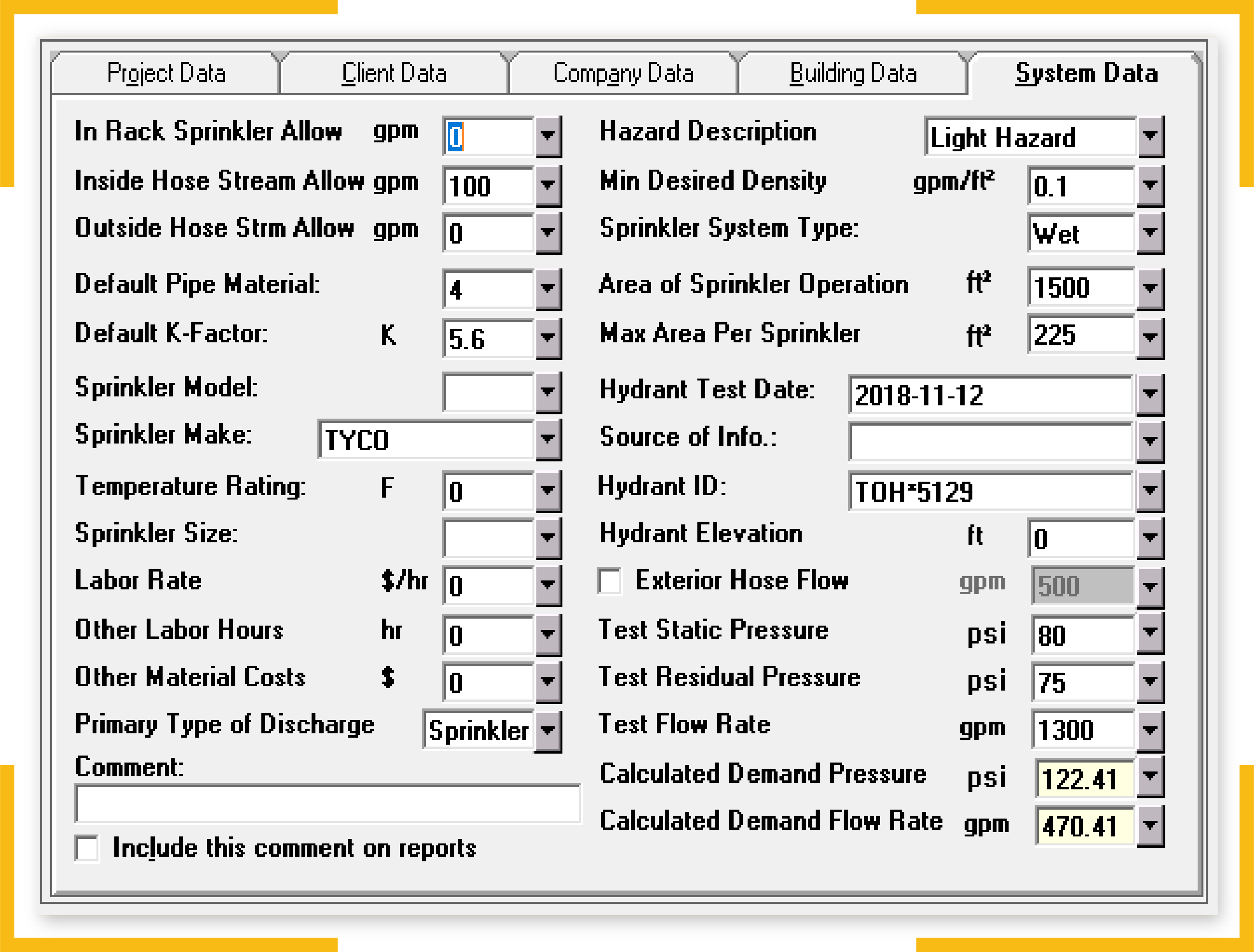
To provide reliable fire protection for a building, an automatic sprinkler system must have a layout that fully covers the building area. This means the system must have a sufficient number of sprinkler heads, and their spatial distribution should achieve full coverage.
However, there is another requirement for effective fire protection: discharging enough water to douse the active fire when sprinkler heads open. The water discharge needed will depend on the area covered, but also the materials present and their vulnerability to fire.
For building occupants, sprinkler heads are the visible part of an automatic sprinkler system. However, there is also a piping network and a water supply that is mostly hidden from sight. The water supply should deliver enough pressure and flow to reach any sprinkler in the building. Fire protection engineers must consider not only the water discharged by sprinklers but also the friction losses that occur when water travels inside a pipe.
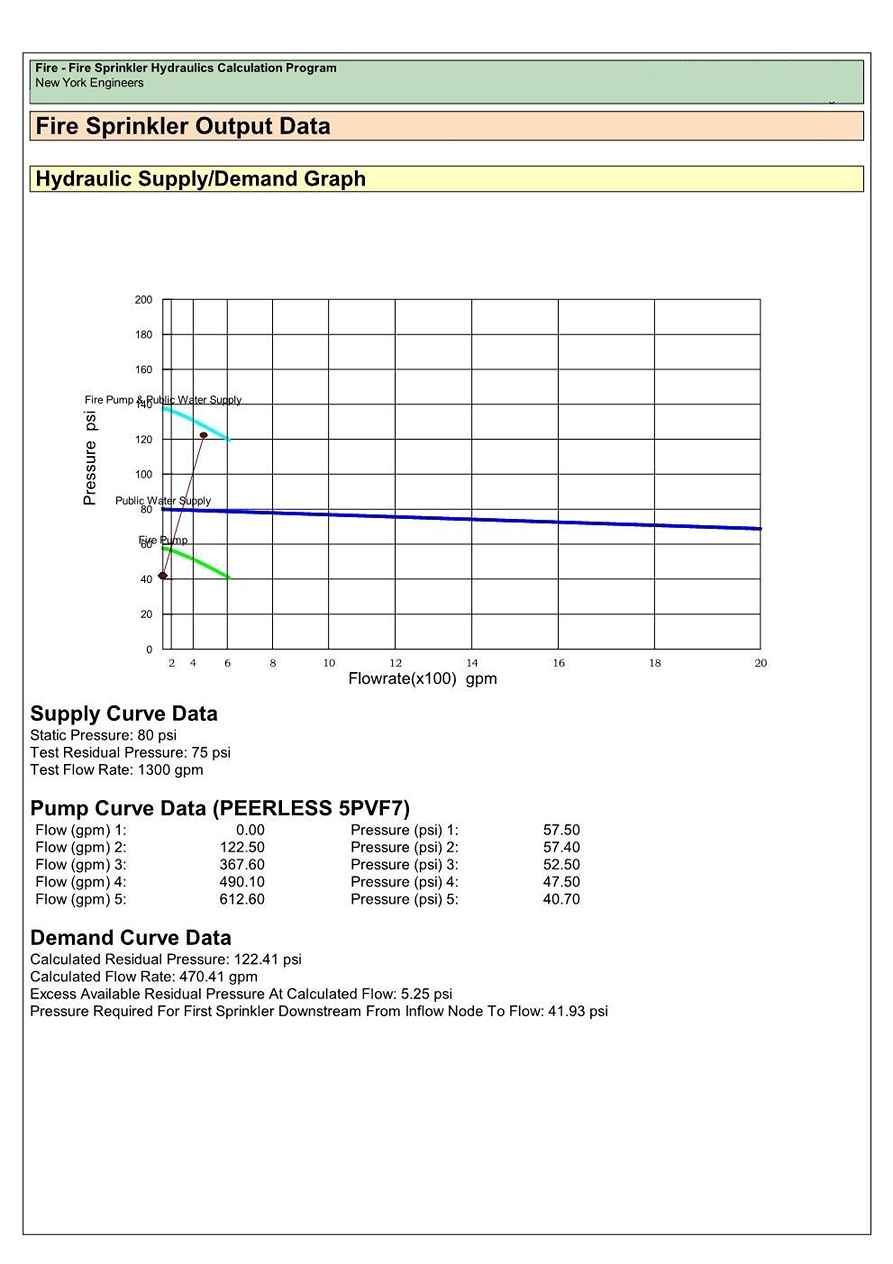
There are two main methods that can be used to calculate the piping diameters of a fire sprinkler system: the pipe schedule method and the hydraulic calculation method.
- Pipe schedule method: The piping diameters are determined from tables, based on the occupancy classification of the building, and the number of sprinklers that can be served with each piping diameter.
- Hydraulic calculation method: The actual pressure losses through the piping system are calculated with the Hazen-Williams method, based on the internal friction of pipes. The piping diameters are selected to ensure that water is discharged from sprinklers at the required pressure and flow. Calculations are more complex with this method, but there are potential savings by using smaller pipes.
The NFPA 13 standard allows the pipe schedule method in some cases, but the hydraulic calculation method is preferred. The pipe schedule method often leads to oversized piping, which brings higher material and installation costs. When the hydraulic calculation method is used instead, material and labor savings of over 20% are possible. The hydraulic method is also more versatile, since it can be used with any piping material, while the pipe schedule method changes depending on the material.
The hydraulic calculation method allows smaller piping diameters while still meeting NFPA 13 and providing reliable fire protection, saving on both materials and labor. Consider that smaller piping also means less weight to handle and smaller fittings, leading to additional savings. A design with hydraulic calculations can also use less piping sizes than the pipe schedule method, and material purchases are easier to manage.
we are providing an overview of how automatic sprinkler systems are designed with the hydraulic calculation method. However, this is not a replacement for the actual requirements of the NFPA 13 standard and local building codes.
Since each building is unique, sprinkler system designs are also unique. However, most piping configurations can be described as a tree, loop or grid.
|
Piping Configuration |
Description |
|
Tree |
The piping that supplies water to the sprinklers branches out from a main line, as the name implies. |
|
Loop |
Piping also branches out from a main line, but it circles back to the water supply. |
|
Grid |
There are several main lines of piping that run parallel to each other, interconnected by smaller piping segment. |
The tree configuration is the simplest, since there is only one path from the water supply to each sprinkler. The loop configuration is slightly more complex, since the water can take two different routes. Finally, the grid layout is the most complex, since there are many possible paths between the water source and each sprinkler. Also, pressures must balance at junction points when there are multiple paths, to ensure that water always flows in the intended direction. Unbalanced pressures can cause unwanted flows, limiting the water supplied to open sprinklers.
Manual calculations are feasible for tree layouts and also for simple loops, but the procedure becomes increasingly complex for grid layouts. However, computer calculations are the standard practice for modern sprinkler designs, regardless of the layout used.
Before specifying the location of any sprinkler heads or pipes, fire protection engineers must determine the occupancy hazard classification of the protected area. However, there is no specific calculation procedure for the occupancy hazard classification, which makes the analysis qualitative. Working with sprinkler system designers who are experienced and familiar with NFPA 13 is recommended, to ensure a proper assessment of the fire hazard.
The occupancy hazard classification answers two important questions, and they are the starting point for the rest of the design procedure:
- How many sprinklers are needed to protect each building area effectively?
- If there is a fire, how many sprinklers can be expected to activate at the same time?
Identifying the occupancy hazard correctly is critical, since the entire design of an automatic sprinkler system depends on this. If the fire hazard is underestimated, sprinklers may be unable to contain the fire, even if the following calculations are accurate. In this case, the initial design requirements are incorrect.
The NFPA 13 standard uses five occupancy hazard classes, and the entire design process of a sprinkler system depends on this selection. Designing the sprinkler layout and the piping network is more complex mathematically, but the occupancy selection is the most critical step:
- Light hazard
- Ordinary hazard, Group 1 and Group 2
- Extra hazard, Group 1 and Group 2
There are additional special classes for fire sprinklers in specific applications. Two examples are the storage commodity classes from I to IV, and the plastics groups from A to C.
The occupancy hazard classification determines the required water discharge for reliable fire protection. This is the starting point for the hydraulic calculation procedure, and identifying the fire hazard correctly is fundamental. An undersized sprinkler system may be overpowered by a fire, while an oversized installation represents a waste of capital.
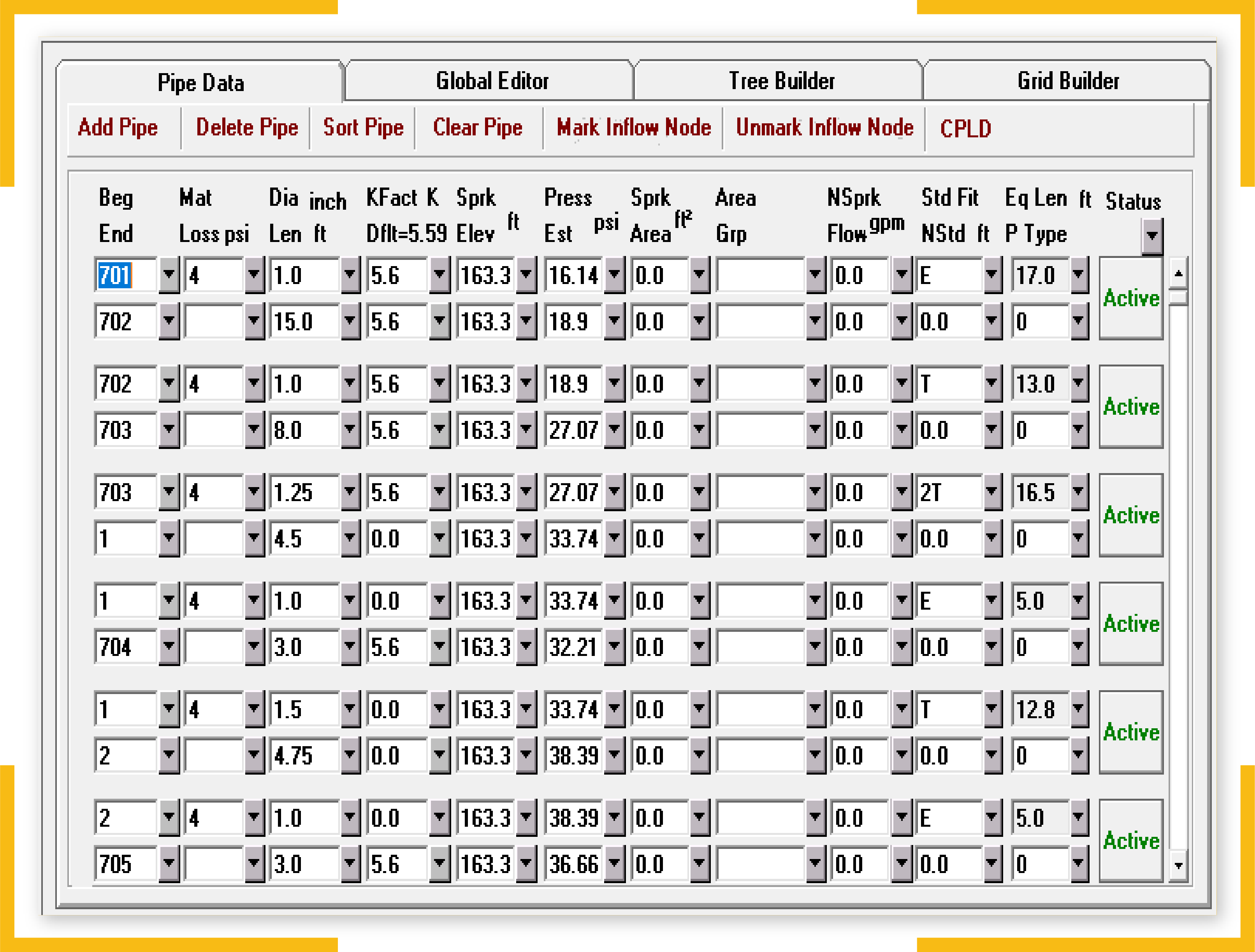
The design density of discharge is the amount of water released by the sprinkler system, per square meter and per minute. This is determined based on floor area and the occupancy hazard classification. The design density of discharge is expressed in millimeters per minute (mm/min), but this unit can be misleading. Actually, the measurement refers to liters per square meter per minute, which simplifies to mm/min:
- 1 L is 1,000,000 mm3
- 1 m2 is 1,000,000 mm2
- Therefore, 1 L/m2 can be simplified to 1 mm
In short, when you see mm/min in a fire sprinkler design, it really means L/m2/min. For example, if the design density is 5 mm/min and the area is 100 m2, the sprinklers must be designed to discharge 500 liters per minute.
Water is widely used for fire protection purposes due to its effectiveness and availability. In many cases, water can control the three basic elements that sustain a fire: oxygen, heat and fuel.
- Oxygen is displaced when water falls on a burning object or surface.
- Heat is removed effectively, since one gallon of water at 70°F absorbs 9,280 BTU before becoming steam. Water has a high specific heat, and also a high latent heat of vaporization.
- Flammable substances do not burn easily once they are soaked with water, especially porous substances that absorb water.
Fluid mechanics is a complex topic, and this includes the equations that model the relationship between fluid pressure and flow. However, fire sprinkler manufacturers use a K-factor to relate pressure and flow with a simple formula:
- Q = K √P
- P = (Q / K)2
There is a minimum design value for both flow and pressure. In the case of water flow (Q), the calculated value may be less than the minimum value provided by the manufacturer. In this case, the sprinkler manufacturer specifications must prevail. The same applies for sprinkler pressure: the NFPA 13 requires at least 7 psi for calculations, even if the formula above results in a lower value (with exceptions).
It is important to note that fire sprinklers have a dual function: they are water distribution nozzles, but they also act as heat sensors. Sprinkler heads only open in response to an active fire or another heat source of the same intensity. The pressure drop and water movement inside the piping also indicate that water is being discharged.
The design of automatic sprinkler systems can vary a lot, since both the fire hazard and the covered area are considered. For instance, a small extra-hazard area may require more water discharge that a large light-hazard area.
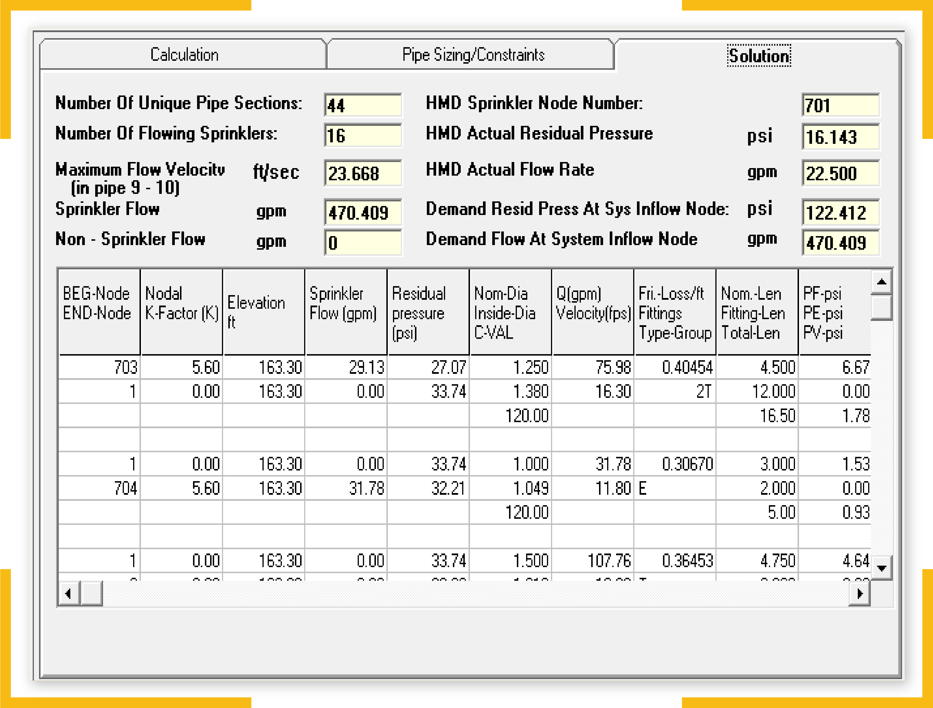
Fire protection engineers can determine the following information with the hydraulic calculation method:
- All the piping diameters required by the automatic sprinkler system.
- The pressure and flow that the water source must deliver, to ensure that the sprinkler system can discharge enough water in response to fire.
However, there may be cases in which the water supply is unable to deliver enough water at the design pressure. If sufficient flow is available but the pressure is low, a fire pump is required to boost pressure. However, the net positive suction head must also be within the pump’s specifications, or otherwise, the unit will be damaged quickly by cavitation.
In spite of its usefulness, water is not a perfect fire-extinguishing agent. Some chemical substances such as lithium will react violently with water, making fires stronger. Water is also unsuitable for fires caused by electrical faults, since it conducts electricity. Fires caused by burning hydrocarbon fuels are also difficult to control with water alone: these fuels can float above the water without mixing, while continuing to burn. In these cases, sprinkler systems are designed to release a water-foam mixture or a different substance.
The usefulness of water is also limited in low-temperature applications, since it may freeze. This issue can be solved by using a dry-pipe sprinkler system, and by adding antifreeze to the water.
The use of a water-foam mixture or an antifreeze solution changes the properties of water, including its density. To achieve reliable fire protection, this must be considered during the design process. In the case of water-foam mixtures, the NFPA 16 standard allows using the density of pure water in many cases. When antifreeze is used, on the other hand, the calculation must be adjusted for density changes. However, the hydraulic calculation method is suitable even when the fire-extinguishing agent is not pure water, since the procedure is based on the frictional losses of piping.
Automatic sprinkler systems are idle most of the time. However, when they must react to a fire, there is zero margin of error. Fire protection engineers must first determine the fire hazard for all areas of the building in question. Then, they must design a sprinkler system that can discharge enough water to extinguish fires of the expected intensity.
Ideally, an automatic sprinkler system should offer reliable fire protection at an optimal cost of ownership. The hydraulic calculation method is very useful for this purpose, since it allows the selection of optimal pipe sizes for the sprinkler layout. On the other hand, the traditional pipe schedule method often leads to oversized installations, which are more expensive.
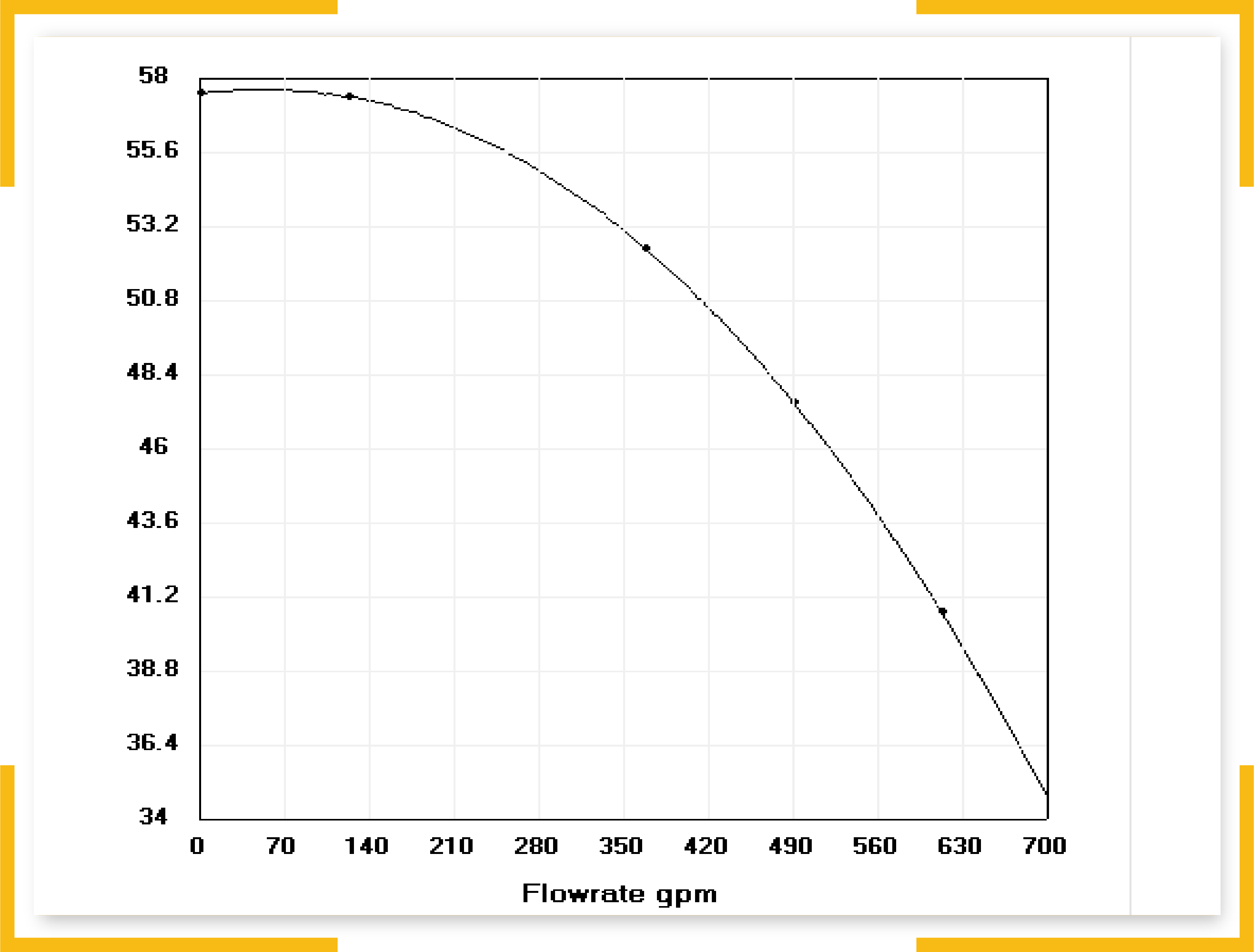
Can Your Sprinkler System Deliver Enough Water?

To provide reliable fire protection for a building, an automatic sprinkler system must have a layout that fully covers the building area. This means the system must have a sufficient number of sprinkler heads, and their spatial distribution should achieve full coverage.
However, there is another requirement for effective fire protection: discharging enough water to douse the active fire when sprinkler heads open. The water discharge needed will depend on the area covered, but also the materials present and their vulnerability to fire.
For building occupants, sprinkler heads are the visible part of an automatic sprinkler system. However, there is also a piping network and a water supply that is mostly hidden from sight. The water supply should deliver enough pressure and flow to reach any sprinkler in the building. Fire protection engineers must consider not only the water discharged by sprinklers but also the friction losses that occur when water travels inside a pipe.
Hydraulic Calculation Methods

There are two main methods that can be used to calculate the piping diameters of a fire sprinkler system: the pipe schedule method and the hydraulic calculation method.
- Pipe schedule method: The piping diameters are determined from tables, based on the occupancy classification of the building, and the number of sprinklers that can be served with each piping diameter.
- Hydraulic calculation method: The actual pressure losses through the piping system are calculated with the Hazen-Williams method, based on the internal friction of pipes. The piping diameters are selected to ensure that water is discharged from sprinklers at the required pressure and flow. Calculations are more complex with this method, but there are potential savings by using smaller pipes.
The NFPA 13 standard allows the pipe schedule method in some cases, but the hydraulic calculation method is preferred. The pipe schedule method often leads to oversized piping, which brings higher material and installation costs. When the hydraulic calculation method is used instead, material and labor savings of over 20% are possible. The hydraulic method is also more versatile, since it can be used with any piping material, while the pipe schedule method changes depending on the material.
The hydraulic calculation method allows smaller piping diameters while still meeting NFPA 13 and providing reliable fire protection, saving on both materials and labor. Consider that smaller piping also means less weight to handle and smaller fittings, leading to additional savings. A design with hydraulic calculations can also use less piping sizes than the pipe schedule method, and material purchases are easier to manage.
we are providing an overview of how automatic sprinkler systems are designed with the hydraulic calculation method. However, this is not a replacement for the actual requirements of the NFPA 13 standard and local building codes.
Types of Piping Layouts for Fire Sprinkler Systems
Since each building is unique, sprinkler system designs are also unique. However, most piping configurations can be described as a tree, loop or grid.
|
Piping Configuration |
Description |
|
Tree |
The piping that supplies water to the sprinklers branches out from a main line, as the name implies. |
|
Loop |
Piping also branches out from a main line, but it circles back to the water supply. |
|
Grid |
There are several main lines of piping that run parallel to each other, interconnected by smaller piping segment. |
The tree configuration is the simplest, since there is only one path from the water supply to each sprinkler. The loop configuration is slightly more complex, since the water can take two different routes. Finally, the grid layout is the most complex, since there are many possible paths between the water source and each sprinkler. Also, pressures must balance at junction points when there are multiple paths, to ensure that water always flows in the intended direction. Unbalanced pressures can cause unwanted flows, limiting the water supplied to open sprinklers.
Manual calculations are feasible for tree layouts and also for simple loops, but the procedure becomes increasingly complex for grid layouts. However, computer calculations are the standard practice for modern sprinkler designs, regardless of the layout used.
Importance of the Occupancy Hazard Classification
Before specifying the location of any sprinkler heads or pipes, fire protection engineers must determine the occupancy hazard classification of the protected area. However, there is no specific calculation procedure for the occupancy hazard classification, which makes the analysis qualitative. Working with sprinkler system designers who are experienced and familiar with NFPA 13 is recommended, to ensure a proper assessment of the fire hazard.
The occupancy hazard classification answers two important questions, and they are the starting point for the rest of the design procedure:
- How many sprinklers are needed to protect each building area effectively?
- If there is a fire, how many sprinklers can be expected to activate at the same time?
Identifying the occupancy hazard correctly is critical, since the entire design of an automatic sprinkler system depends on this. If the fire hazard is underestimated, sprinklers may be unable to contain the fire, even if the following calculations are accurate. In this case, the initial design requirements are incorrect.
The NFPA 13 standard uses five occupancy hazard classes, and the entire design process of a sprinkler system depends on this selection. Designing the sprinkler layout and the piping network is more complex mathematically, but the occupancy selection is the most critical step:
- Light hazard
- Ordinary hazard, Group 1 and Group 2
- Extra hazard, Group 1 and Group 2
There are additional special classes for fire sprinklers in specific applications. Two examples are the storage commodity classes from I to IV, and the plastics groups from A to C.
The occupancy hazard classification determines the required water discharge for reliable fire protection. This is the starting point for the hydraulic calculation procedure, and identifying the fire hazard correctly is fundamental. An undersized sprinkler system may be overpowered by a fire, while an oversized installation represents a waste of capital.
How Much Water is Discharged by Fire Sprinklers?

The design density of discharge is the amount of water released by the sprinkler system, per square meter and per minute. This is determined based on floor area and the occupancy hazard classification. The design density of discharge is expressed in millimeters per minute (mm/min), but this unit can be misleading. Actually, the measurement refers to liters per square meter per minute, which simplifies to mm/min:
- 1 L is 1,000,000 mm3
- 1 m2 is 1,000,000 mm2
- Therefore, 1 L/m2 can be simplified to 1 mm
In short, when you see mm/min in a fire sprinkler design, it really means L/m2/min. For example, if the design density is 5 mm/min and the area is 100 m2, the sprinklers must be designed to discharge 500 liters per minute.
Water is widely used for fire protection purposes due to its effectiveness and availability. In many cases, water can control the three basic elements that sustain a fire: oxygen, heat and fuel.
- Oxygen is displaced when water falls on a burning object or surface.
- Heat is removed effectively, since one gallon of water at 70°F absorbs 9,280 BTU before becoming steam. Water has a high specific heat, and also a high latent heat of vaporization.
- Flammable substances do not burn easily once they are soaked with water, especially porous substances that absorb water.
Fluid mechanics is a complex topic, and this includes the equations that model the relationship between fluid pressure and flow. However, fire sprinkler manufacturers use a K-factor to relate pressure and flow with a simple formula:
- Q = K √P
- P = (Q / K)2
There is a minimum design value for both flow and pressure. In the case of water flow (Q), the calculated value may be less than the minimum value provided by the manufacturer. In this case, the sprinkler manufacturer specifications must prevail. The same applies for sprinkler pressure: the NFPA 13 requires at least 7 psi for calculations, even if the formula above results in a lower value (with exceptions).
It is important to note that fire sprinklers have a dual function: they are water distribution nozzles, but they also act as heat sensors. Sprinkler heads only open in response to an active fire or another heat source of the same intensity. The pressure drop and water movement inside the piping also indicate that water is being discharged.
The design of automatic sprinkler systems can vary a lot, since both the fire hazard and the covered area are considered. For instance, a small extra-hazard area may require more water discharge that a large light-hazard area.
How Hydraulic Calculations Affect the Water Supply Requirements

Fire protection engineers can determine the following information with the hydraulic calculation method:
- All the piping diameters required by the automatic sprinkler system.
- The pressure and flow that the water source must deliver, to ensure that the sprinkler system can discharge enough water in response to fire.
However, there may be cases in which the water supply is unable to deliver enough water at the design pressure. If sufficient flow is available but the pressure is low, a fire pump is required to boost pressure. However, the net positive suction head must also be within the pump’s specifications, or otherwise, the unit will be damaged quickly by cavitation.
Hydraulic Calculations for Water-Foam Mixtures and Antifreeze Solutions
In spite of its usefulness, water is not a perfect fire-extinguishing agent. Some chemical substances such as lithium will react violently with water, making fires stronger. Water is also unsuitable for fires caused by electrical faults, since it conducts electricity. Fires caused by burning hydrocarbon fuels are also difficult to control with water alone: these fuels can float above the water without mixing, while continuing to burn. In these cases, sprinkler systems are designed to release a water-foam mixture or a different substance.
The usefulness of water is also limited in low-temperature applications, since it may freeze. This issue can be solved by using a dry-pipe sprinkler system, and by adding antifreeze to the water.
The use of a water-foam mixture or an antifreeze solution changes the properties of water, including its density. To achieve reliable fire protection, this must be considered during the design process. In the case of water-foam mixtures, the NFPA 16 standard allows using the density of pure water in many cases. When antifreeze is used, on the other hand, the calculation must be adjusted for density changes. However, the hydraulic calculation method is suitable even when the fire-extinguishing agent is not pure water, since the procedure is based on the frictional losses of piping.
Conclusion
Automatic sprinkler systems are idle most of the time. However, when they must react to a fire, there is zero margin of error. Fire protection engineers must first determine the fire hazard for all areas of the building in question. Then, they must design a sprinkler system that can discharge enough water to extinguish fires of the expected intensity.
Ideally, an automatic sprinkler system should offer reliable fire protection at an optimal cost of ownership. The hydraulic calculation method is very useful for this purpose, since it allows the selection of optimal pipe sizes for the sprinkler layout. On the other hand, the traditional pipe schedule method often leads to oversized installations, which are more expensive.


