
5 Days- That's a Lightning Fast Turnaround Time!
1
Upload Files and Pay
Upload PDF or CAD files, and pay to start the process. An engineer is auto-assigned to your project.
2
Document Review
An engineer will review all the documents shared and connect with you if anything else is required. Initial work starts.
3
Work Starts
Actual design/ report creation work begins.
4
Quality Check
The design and report are checked by the project manager to make sure 100% quality work is delivered.
5
Delivery
The design/ report is delivered to you.
Get Your Redline Markup Drawing In 3 Easy Steps
Documents Required
Red line/ hand markups and photos.
Delivery Time & Standards
We deliver your CAD design (digitally) within 5 business days.
What's not Covered
This service does not cover site visits, stamping, DOB/DEP filing, and more than 2 minor iterations.
Service Constraint
The service fee is limited to 3,000 sq. ft.* of floor plan.
$750*
Redline markup to CAD
Get the CAD drawings at lightning speed.

Avoid redrawing the design.

Precise conversion to CAD as per design shared.

CAD conversion for all MEP/ FP designs.
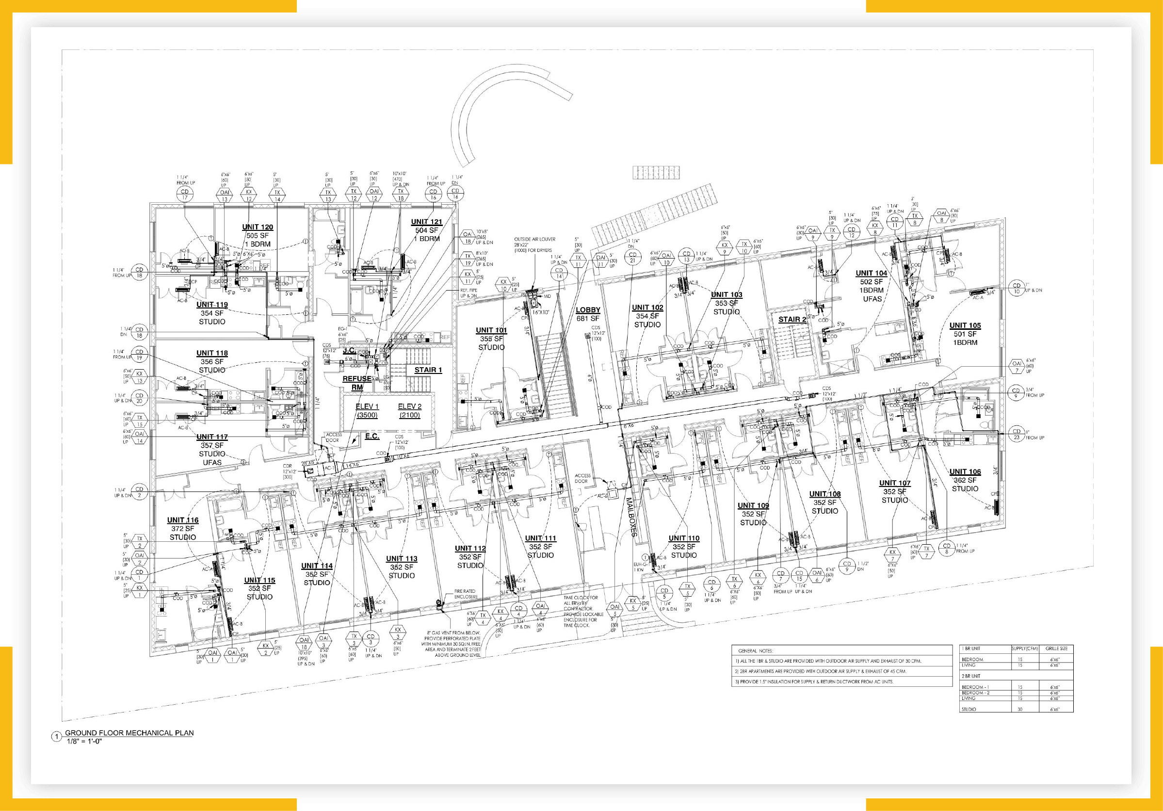
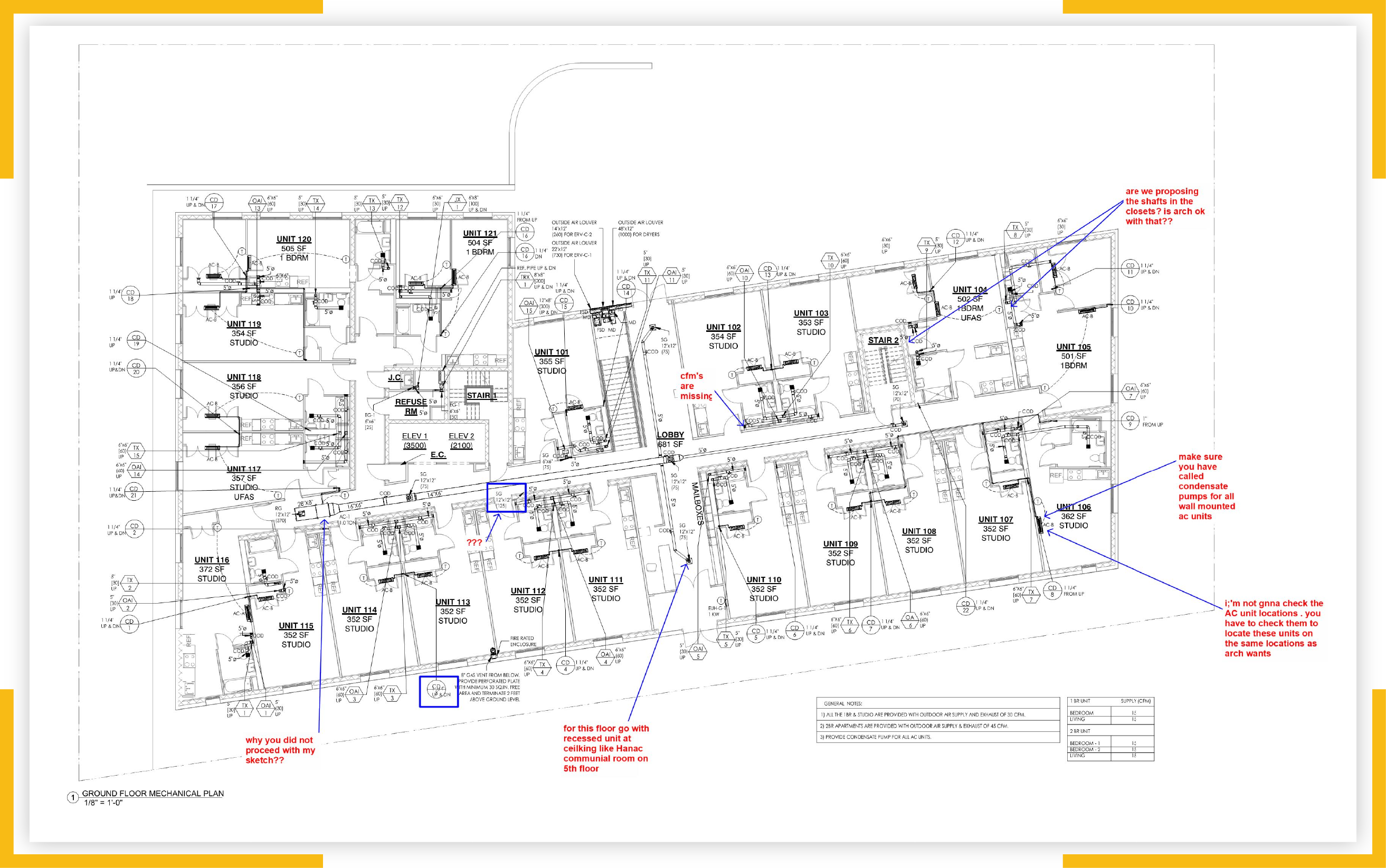
Redline Markup Drawing into CAD


Convert From Sketch to CAD
If you have sketches or plans that have redline markup, we can convert these to 2D and 3D computer-aided design (CAD) in the form of AutoCAD, or to Revit if the next step for your designer is building information modeling (BIM).
Incorporate Design Changes
Redline markup is a brilliant way to share files for online collaboration whether for building or for renovations, alternations, or maintenance. The markups are added, on a computer, when the drawings are amended or redrafted.
Modifications for As-Built Drawings
Ensure that all modifications and deviations from existing plans are correctly identified before as-built drawings are prepared. This is part of the exacting preparatory process that our experienced team will take care of.


Our on-demand engineering expert
Still not sure about how to proceed?
YOU CAN WRITE TO ME AT inquiry@ny-engineers.com
In the past two or more decades there has been an intensive shift by engineering companies towards whole-product lifestyle support and collaboration. As a result, it has become increasingly important to capture knowledge and information and to record experiences that relate to previous design and the subsequent stages of the lifecycle of products to be able to retrieve and reuse information.
As digital technologies have developed rapidly, annotation and markup have become increasingly important tools in the industry. There are numerous techniques in use for different applications and digital items including text documents, 2D images, and 3D models.
A particularly important element is that increasingly, many projects involve designers and other professionals who are located in different, even disparate, locations. The challenge is for them to be able to work together, not necessarily physically, but by using technologies that support engineering design.
By adding annotations to design drawings, engineers are able to communicate with their colleagues and provide them with commentaries, additional descriptions, and interpretations of different viewpoints. Markup is regarded as a type of annotation that is formally structured.
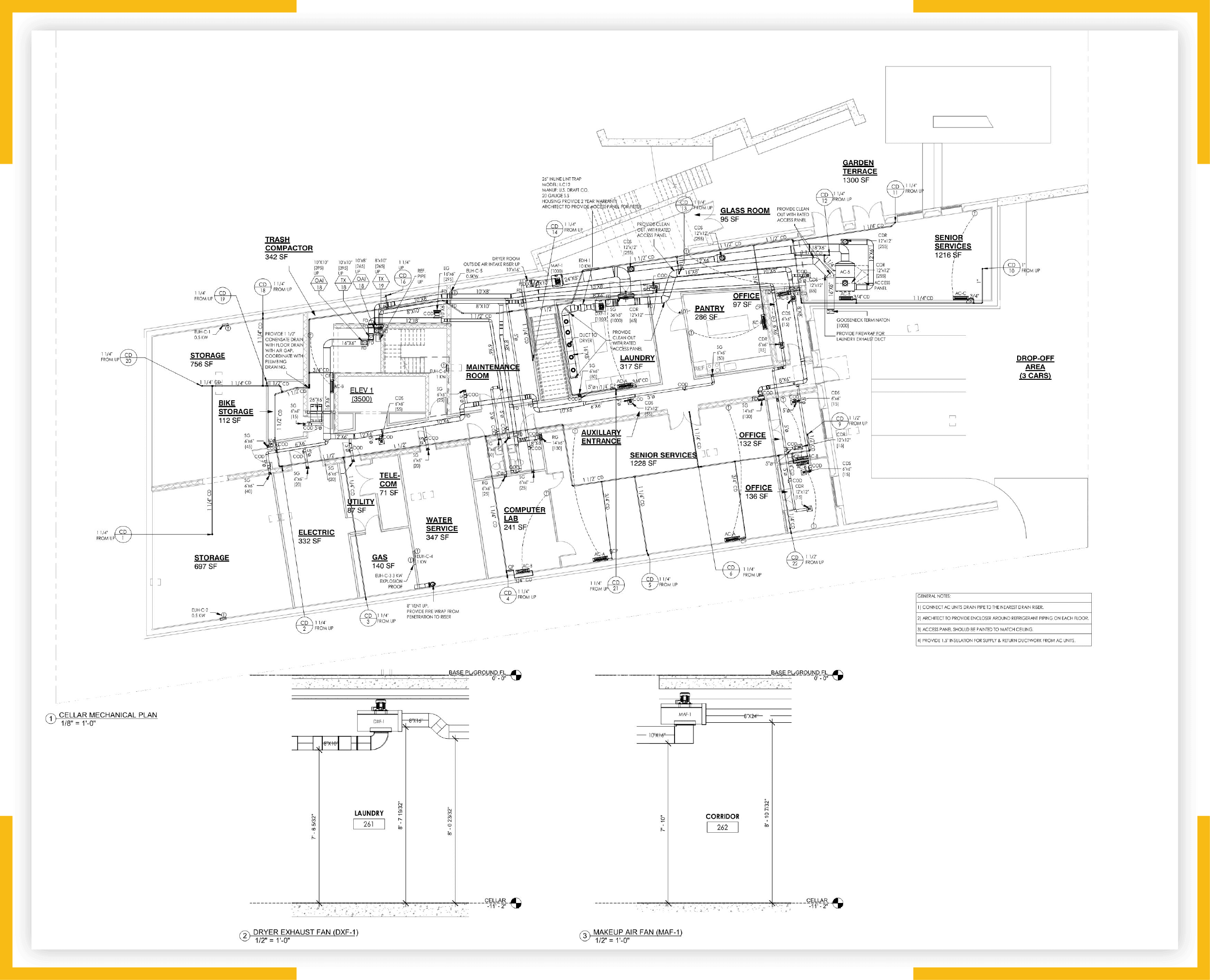
We can apply redline markup (Hand Markup) in various different formats, providing the markup files as scanned images, hard-copy drawings, drawn with markup written by hand, or in an Adobe file.
Redline or hand markup is commonly used to mark-up corrections on existing architectural drawings that relate to engineering designs. It provides an ideal tool to coordinate the drawing review process among the various stakeholders, including structural engineers, MEP professionals, and the various contractors who are involved in the project.
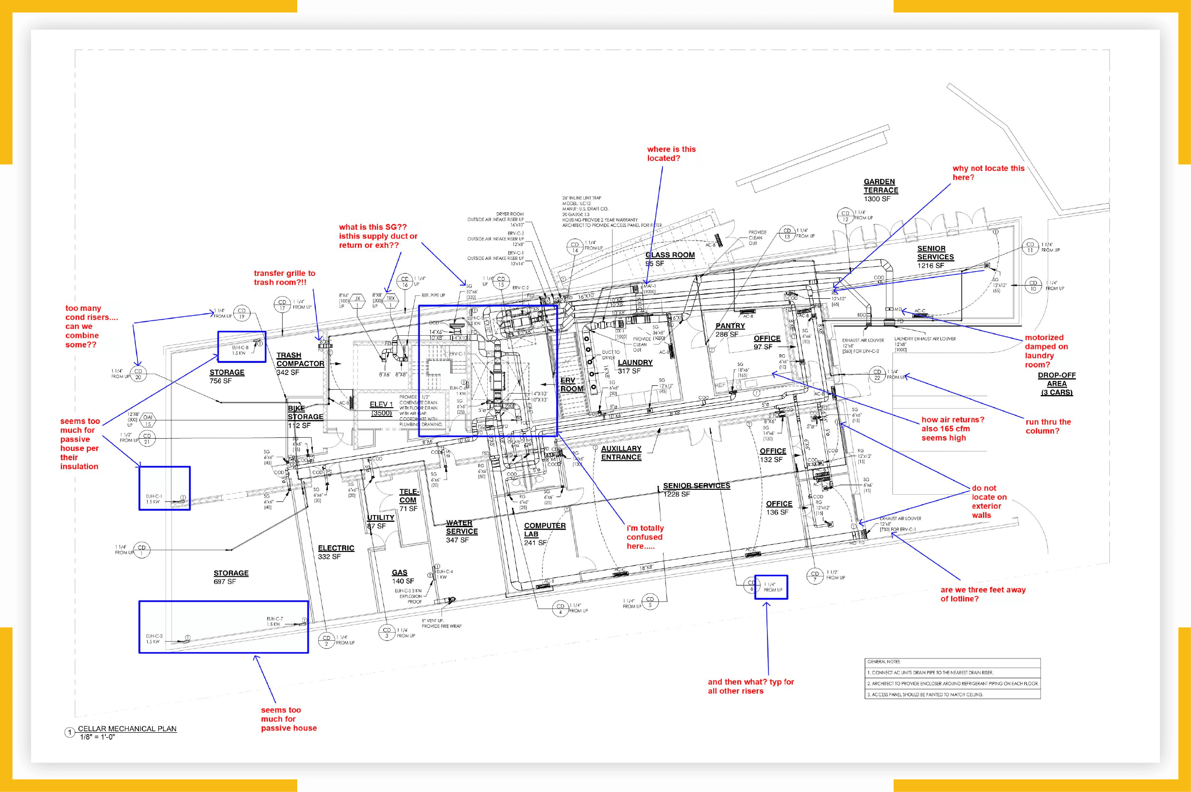
Drawing its name from the traditional hand-drawn technique of using a red pen to indicate corrections and changes on plans, drawings, and other construction documents, redline markup is an invaluable tool.
However, redline engineering drawings are challenging and it is essential that they are planned and executed so there aren’t any unnecessary delays that might affect the construction process.
While redline markup is often used to make corrections to drawings, it is also used to improve drawings and to add effective resolutions when problems have been detected. Markup in the form of annotations also allows stakeholders and team members to contribute their input.
Redline and hand markup is also used to identify areas of conflict, for instance when we undertake clash detection/resolution services to streamline construction processes and reduce the financial and other on-site risks that might result.
Redline markup on drawings helps the professional construction team to envisage the correct plans. They also constitute an effective means of preventing the need for rework during construction – which effectively saves time and money.
Markups are often provided in sketches and we design according to these or as the details are shown in other Redline markup documents. Clash detection and clash resolution are other services that we provide, to prevent issues that might impact on projects at a later stage.
Not that long ago, the markup required was done manually on plans and drawings. It was an accurate process but time-consuming. Over time, there has been an increase in semi-automatic and automatic methods, including those that we can convert to AutoCAD and Revit with relative ease.
Early conventional markup was implemented with in-line notations that were merged into text documents. Like contemporary hand markup, this type of markup is noticeable because the annotations are a different color to the original text, usually red. Although easy to implement, if the markup is embedded in the document, it often changes the way the document appears, and it can interfere with other sets of markup.
Another relatively early method of markup, known as stand-off, involves separate external documents that reference or point to the element within the text document or digital object to which it refers.
One advantage is that multiple markup layers can be added to documents and/or digital models allowing them to expand without changing whatever representation method was used for the original object. This makes it a good tool for updating information throughout the lifecycle of a product. Another is that different viewpoints can be incorporated, which is invaluable since there are often multiple different opinions and ideas on how work should proceed.
The disadvantage of stand-off markup is that it is difficult to implement and persistent references can be problematic.
As 3D digital product models have continued to dominate industry design, the markup for computer-aided design (CAD) has become increasingly sophisticated and more reliable. For example, designers can navigate and markup models in Autodesk Viewer if they are using Design Web Format (DWF), for instance in Revit.
Our skilled team can apply redline markup to plans and drawings. But to be able to review the drawings, it is essential for hand markups to be correctly incorporated into AutoCAD or Revit drawings. The highly qualified engineering team at NY Engineers prepares design drawings in CAD and Revit and we are available to convert from scanned images, hard copy drawings, hand-written markups, or redline markups that have been created in a variety of other programs.
NY Engineers offers CAD and Revit modeling engineering services as well as low-cost Revit drafting services with very quick turnaround times. We use both types of software for converting redline and hand markup into a more useful format.
The main difference between the two applications, both of which are types of Autodesk software, is that:
AutoCAD
AutoCAD is a general computer-aided design and drafting software that is intended for creating very precise 2D and 3D drawings. It is also used for 3D modeling and visualization.
Some of the features that illustrate what can be achieved with AutoCAD include:
- Creation and editing of 2D geometry.
- Creating and editing 3D models that have a variety of objects including surfaces, solids, and mesh.
- Annotation of drawings and inclusion of text, dimensions, tables, and other elements. This is key for markup functions.
- Customization of tool palettes and the ribbon.
- Customization with application programming interfaces (APIs) and various add-on applications.
- Extraction of object data for utilization in tables.
- Usage of data from pdf files.
- Sharing and usage of data from Navisworks, Bing Maps, and DGN 2D/3D drawing files created with construction CAD software.
- Application and monitoring of the various CAD standards that improve the interchangeability of CAD documents as well as general productivity.
Redline markups are commonly used with AutoCAD because it makes it so easy for people to work together and to collaborate by sharing files online. Of course, AutoCAD has many other tools that assist with online collaboration. They also help to effectively track workflow and enable people to go back in time and track all the changes that have ever been made to files.
Revit
Revit is much more sophisticated building-specific software for building information modeling (BIM) that has tools that allow us to create “intelligent” 3D models of buildings. It is popular for architectural design, preconstruction design, and for both structural engineering and MEP engineering and detailing.
Some of the features that illustrate what can be achieved with Revit include:
- Conceptualization of design.
- 3D parametric modeling.
- Documentation of detailed design work.
- Multidisciplinary coordination.
- Modeling of the full spectrum of building components.
- Simulations and analysis of systems and structures relevant to construction.
- Visualization and iteration of designs of various types.
- Generation of documentation for fabrication and/or construction designs.
- Modeling of structural steel and its documentation.
- Fabrication modeling and detailing of mechanical, electrical, and plumbing (MEP).
- Visualization of photorealistic 3D models.
- Analysis of building performance.
- Documentation of the construction process.
Contractors often come to us with hand sketches and want them converted to Revit because it supports BIM workflows. While there is nothing to stop them from using hand drawings and sketches throughout the construction process, the technology progression that enables process and workflow changes when using BIM has major advantages, particularly in terms of integration and collaboration between the various professionals.
An outstanding benefit is that the software creates silos so that the 3D models can progress at different rates, through different design and engineering phases, allowing stakeholders who aren’t necessarily physically on the job to participate and provide input.
While it is possible to identify everything on flat plans and drawings, the complexity of the various elements – underground pipework for example – is impossible to show. It is even difficult in 2D design, which is why we are seeing an ever-increasing shift to 3D models. The move to BIM (via Revit or any other software) can be daunting, but the relationship between objects and elements is maintained in 3D models instead of being locked into a myriad of design sheets that need to be constantly updated with hand markup.
Moving from hand-drawn plans, sketches, and even computerized redline markup to BIM requires engineers to interface with complex models rather than just do sketches and accompanying calculations. It’s a quantum leap for many, requiring increased resources to be able to enact new approaches. But it brings multiple disciplines together and forces people to collaborate a lot earlier in the lifecycle of projects. Ultimately, this will lead to shared responsibility.
But there is still a place for less complex CAD, and it is common for engineering companies like NY Engineers to use both programs (CAD and Revit) because they can be used together. So we are able to incorporate designs that we have created in AutoCAD and use these in Revit projects, and vice versa.
Autodesk tools for both AutoCAD and Revit increase our ability to find specialized solutions too. For instance, we now use access-integrated BIM and CAD technologies for civil infrastructure and building design, construction, and engineering. This enables us to integrate workflows for infrastructure and building projects and to maintain consistent design models throughout our projects using integrated tools. We can also use visual logic to automate tasks and design all-important workflows. Then, as time moves on and the project progresses, we can verify and speed review workflows.
We can plan and design with real-world data and powerful 3D models which provide us with incredibly realistic images. We are able to connect preliminary as well as conceptual design to detailed engineering and fabrication processes.
So, whether you are simply looking for customized architectural drafting services like redline or hand markup into CAD or you need an experienced company that offers a wide range of BIM services including drawings, energy analysis, or detection and resolution of clashes, you’ve come to the right place.
has a committed team of engineers that works in the full range of construction projects including commercial and all types of residential. Contact us via email or call to schedule an appointment.
Annotation & Markup
In the past two or more decades there has been an intensive shift by engineering companies towards whole-product lifestyle support and collaboration. As a result, it has become increasingly important to capture knowledge and information and to record experiences that relate to previous design and the subsequent stages of the lifecycle of products to be able to retrieve and reuse information.
As digital technologies have developed rapidly, annotation and markup have become increasingly important tools in the industry. There are numerous techniques in use for different applications and digital items including text documents, 2D images, and 3D models.
A particularly important element is that increasingly, many projects involve designers and other professionals who are located in different, even disparate, locations. The challenge is for them to be able to work together, not necessarily physically, but by using technologies that support engineering design.
By adding annotations to design drawings, engineers are able to communicate with their colleagues and provide them with commentaries, additional descriptions, and interpretations of different viewpoints. Markup is regarded as a type of annotation that is formally structured.
We can apply redline markup (Hand Markup) in various different formats, providing the markup files as scanned images, hard-copy drawings, drawn with markup written by hand, or in an Adobe file.
Redline & Hand Markup
Redline or hand markup is commonly used to mark-up corrections on existing architectural drawings that relate to engineering designs. It provides an ideal tool to coordinate the drawing review process among the various stakeholders, including structural engineers, MEP professionals, and the various contractors who are involved in the project.
Drawing its name from the traditional hand-drawn technique of using a red pen to indicate corrections and changes on plans, drawings, and other construction documents, redline markup is an invaluable tool.
However, redline engineering drawings are challenging and it is essential that they are planned and executed so there aren’t any unnecessary delays that might affect the construction process.
While redline markup is often used to make corrections to drawings, it is also used to improve drawings and to add effective resolutions when problems have been detected. Markup in the form of annotations also allows stakeholders and team members to contribute their input.
Redline and hand markup is also used to identify areas of conflict, for instance when we undertake clash detection/resolution services to streamline construction processes and reduce the financial and other on-site risks that might result.
Redline markup on drawings helps the professional construction team to envisage the correct plans. They also constitute an effective means of preventing the need for rework during construction – which effectively saves time and money.
Markups are often provided in sketches and we design according to these or as the details are shown in other Redline markup documents. Clash detection and clash resolution are other services that we provide, to prevent issues that might impact on projects at a later stage.
Types of Markup
Not that long ago, the markup required was done manually on plans and drawings. It was an accurate process but time-consuming. Over time, there has been an increase in semi-automatic and automatic methods, including those that we can convert to AutoCAD and Revit with relative ease.
Early conventional markup was implemented with in-line notations that were merged into text documents. Like contemporary hand markup, this type of markup is noticeable because the annotations are a different color to the original text, usually red. Although easy to implement, if the markup is embedded in the document, it often changes the way the document appears, and it can interfere with other sets of markup.
Another relatively early method of markup, known as stand-off, involves separate external documents that reference or point to the element within the text document or digital object to which it refers.
One advantage is that multiple markup layers can be added to documents and/or digital models allowing them to expand without changing whatever representation method was used for the original object. This makes it a good tool for updating information throughout the lifecycle of a product. Another is that different viewpoints can be incorporated, which is invaluable since there are often multiple different opinions and ideas on how work should proceed.
The disadvantage of stand-off markup is that it is difficult to implement and persistent references can be problematic.
As 3D digital product models have continued to dominate industry design, the markup for computer-aided design (CAD) has become increasingly sophisticated and more reliable. For example, designers can navigate and markup models in Autodesk Viewer if they are using Design Web Format (DWF), for instance in Revit.
Our skilled team can apply redline markup to plans and drawings. But to be able to review the drawings, it is essential for hand markups to be correctly incorporated into AutoCAD or Revit drawings. The highly qualified engineering team at NY Engineers prepares design drawings in CAD and Revit and we are available to convert from scanned images, hard copy drawings, hand-written markups, or redline markups that have been created in a variety of other programs.
AutoCAD & Revit
NY Engineers offers CAD and Revit modeling engineering services as well as low-cost Revit drafting services with very quick turnaround times. We use both types of software for converting redline and hand markup into a more useful format.
The main difference between the two applications, both of which are types of Autodesk software, is that:
AutoCAD
AutoCAD is a general computer-aided design and drafting software that is intended for creating very precise 2D and 3D drawings. It is also used for 3D modeling and visualization.
Some of the features that illustrate what can be achieved with AutoCAD include:
- Creation and editing of 2D geometry.
- Creating and editing 3D models that have a variety of objects including surfaces, solids, and mesh.
- Annotation of drawings and inclusion of text, dimensions, tables, and other elements. This is key for markup functions.
- Customization of tool palettes and the ribbon.
- Customization with application programming interfaces (APIs) and various add-on applications.
- Extraction of object data for utilization in tables.
- Usage of data from pdf files.
- Sharing and usage of data from Navisworks, Bing Maps, and DGN 2D/3D drawing files created with construction CAD software.
- Application and monitoring of the various CAD standards that improve the interchangeability of CAD documents as well as general productivity.
Redline markups are commonly used with AutoCAD because it makes it so easy for people to work together and to collaborate by sharing files online. Of course, AutoCAD has many other tools that assist with online collaboration. They also help to effectively track workflow and enable people to go back in time and track all the changes that have ever been made to files.
Revit
Revit is much more sophisticated building-specific software for building information modeling (BIM) that has tools that allow us to create “intelligent” 3D models of buildings. It is popular for architectural design, preconstruction design, and for both structural engineering and MEP engineering and detailing.
Some of the features that illustrate what can be achieved with Revit include:
- Conceptualization of design.
- 3D parametric modeling.
- Documentation of detailed design work.
- Multidisciplinary coordination.
- Modeling of the full spectrum of building components.
- Simulations and analysis of systems and structures relevant to construction.
- Visualization and iteration of designs of various types.
- Generation of documentation for fabrication and/or construction designs.
- Modeling of structural steel and its documentation.
- Fabrication modeling and detailing of mechanical, electrical, and plumbing (MEP).
- Visualization of photorealistic 3D models.
- Analysis of building performance.
- Documentation of the construction process.
Contractors often come to us with hand sketches and want them converted to Revit because it supports BIM workflows. While there is nothing to stop them from using hand drawings and sketches throughout the construction process, the technology progression that enables process and workflow changes when using BIM has major advantages, particularly in terms of integration and collaboration between the various professionals.
An outstanding benefit is that the software creates silos so that the 3D models can progress at different rates, through different design and engineering phases, allowing stakeholders who aren’t necessarily physically on the job to participate and provide input.
While it is possible to identify everything on flat plans and drawings, the complexity of the various elements – underground pipework for example – is impossible to show. It is even difficult in 2D design, which is why we are seeing an ever-increasing shift to 3D models. The move to BIM (via Revit or any other software) can be daunting, but the relationship between objects and elements is maintained in 3D models instead of being locked into a myriad of design sheets that need to be constantly updated with hand markup.
Moving From Sketches & Redline Markup to BIM
Moving from hand-drawn plans, sketches, and even computerized redline markup to BIM requires engineers to interface with complex models rather than just do sketches and accompanying calculations. It’s a quantum leap for many, requiring increased resources to be able to enact new approaches. But it brings multiple disciplines together and forces people to collaborate a lot earlier in the lifecycle of projects. Ultimately, this will lead to shared responsibility.
But there is still a place for less complex CAD, and it is common for engineering companies like NY Engineers to use both programs (CAD and Revit) because they can be used together. So we are able to incorporate designs that we have created in AutoCAD and use these in Revit projects, and vice versa.
Autodesk tools for both AutoCAD and Revit increase our ability to find specialized solutions too. For instance, we now use access-integrated BIM and CAD technologies for civil infrastructure and building design, construction, and engineering. This enables us to integrate workflows for infrastructure and building projects and to maintain consistent design models throughout our projects using integrated tools. We can also use visual logic to automate tasks and design all-important workflows. Then, as time moves on and the project progresses, we can verify and speed review workflows.
We can plan and design with real-world data and powerful 3D models which provide us with incredibly realistic images. We are able to connect preliminary as well as conceptual design to detailed engineering and fabrication processes.
So, whether you are simply looking for customized architectural drafting services like redline or hand markup into CAD or you need an experienced company that offers a wide range of BIM services including drawings, energy analysis, or detection and resolution of clashes, you’ve come to the right place.
has a committed team of engineers that works in the full range of construction projects including commercial and all types of residential. Contact us via email or call to schedule an appointment.
