Top 3 Operating Modes of VRF Systems

Variable Refrigerant Flow (VRF) is an air conditioning technology that achieves an extremely high efficiency by varying the flow of refrigerant to indoor units, based on the exact demand of each individual area. This ability to control the flow of refrigerant makes VRF systems ideal for applications with varying loads. In addition, VRF systems can also provide space heating, consolidating two building systems in one and saving space.
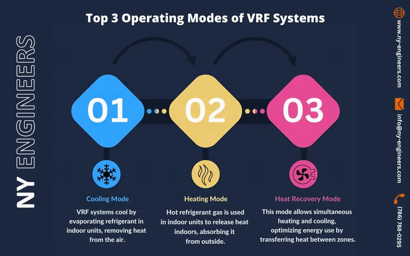
VRF technology is available in two versions - heat pump systems and heat recovery systems. Heat pump VRF systems can either cool or heat the entire building, but cannot perform both functions at the same time. Heat recovery systems do not have this limitation and can serve simultaneous heating and cooling loads, thus leading to 3 different modes of operation:
- Cooling mode
- Heating mode
- Simultaneous cooling & heating, or heat recovery mode
VRF Systems in Cooling Mode
In cooling mode, VRF operation is not very different from that of an air conditioning system: indoor units are supplied with liquid refrigerant, and an expansion valve inside each unit controls the amount of refrigerant flowing through. When refrigerant enters the cooling coil, it undergoes evaporation, removing heat from indoor air and thereby cooling the room. The heat extracted from indoor spaces is then rejected outdoors.
VRF systems are much more efficient than conventional packaged rooftop units (RTU), packaged terminal air conditioners (PTAC) and window units. Ductless mini-split systems and water-cooled chillers offer a similar efficiency in cooling mode, but are unable to operate in heating mode.
VRF Systems in Heating Mode
Unlike cooling mode, where indoor units receive liquid refrigerant, here they are supplied with hot gas refrigerant. Gas flow to individual units is controlled with the same electronic expansion valves used for cooling mode, and the heating effect occurs when hot gas undergoes condensation. The basic principle is still the refrigeration cycle, with the difference that heat is absorbed from outdoors and rejected indoors; in simple terms it is like air-conditioning the cooler outdoor environment to remove heat from it and use it indoors. This operating mode change is made possible with special 4-way reversing valves, which exchange the roles of evaporator and condenser between indoor and outdoor units.
In heating mode, the electric power consumed becomes useful heat, while in cooling mode it is rejected outdoors. Thus, a VRF outdoor unit can operate above 100% of its rated capacity when in heating mode. However, it is also important to note that the capacity may be derated, especially when the system is subject to a large variation in outdoor conditions. Longer piping lengths, longer distances between the outdoor unit and the last indoor unit, and higher vertical separation are some other causes of derating.

VRF Systems in Heat Recovery Mode
A heat recovery system is ideal when simultaneous heating and cooling are required. The greatest efficiency is achieved when the heating and cooling loads are equal, by maximizing the amount of energy transferred from one zone to another using the refrigerant. Heat rejection from cooling spaces can be utilized for space heating in the areas that need it at the same time. Thanks to this configuration, each occupant is free to choose either cooling or heating mode.
Heat recovery systems are very useful when a building has an east-west or south-north orientation with glass façades. East-west and south-north orientations cause a large difference in load requirements for each direction during the morning and evening, providing a chance for the VRF system to operate in simultaneous heating and cooling mode. Heat recovery is particularly useful in buildings with electrical rooms or data centers that need permanent cooling, since they also become a constant source of heat.
Heat Recovery System Piping Configurations
Heat recovery systems come in 2-pipe and 3-pipe configurations, where the 2-pipe system is the option requiring the highest refrigerant flow. To operate with reduced flow, the 3-pipe system has a liquid line, a high-pressure gas line and a low-pressure gas line. The control function is achieved with a Mode Change Unit (MCU) or Mode Selection Box, which has three headers for high-pressure gas, low-pressure gas, and liquid.
- When there are zones that need space heating, their indoor units work like condensers, supplying heat from the condensation of high-pressure refrigerant gas. After heating, the saturated refrigerant is fed to the liquid header.
- Liquid refrigerant is then supplied to the units in space cooling mode, where it evaporates and absorbs heat, becoming a low-pressure gas.
- The low-pressure gas is returned to its respective header and then to the compressor, repeating the cycle.
In this case, the outdoor unit must only provide the balance between heating and cooling - the one that is higher will determine the operating mode of the outdoor unit.
- If cooling load is higher, the outdoor unit operates as a condenser, rejecting the surplus heat outdoors.
- If the heating load is higher, the outdoor units operates as an evaporator, drawing from outdoor air the extra heat needed inside.
The best recommendation is locate the MCU in a public access area such as a corridor, thus minimizing noise and disruption for the end user. Maintenance of heat recovery systems is relatively easy, since the outdoor condenser unit is only connected to the MCU, facilitating system separation into upstream and downstream portions.
As per ASHRAE Standard 34-2013, the refrigerant concentration limit (RCL) is 26 lb per 1,000 ft3 of room volume for occupied spaces, and 13 lb per 1,000 ft3 for institutional buildings. This can be easily achieved by locating the units outside of compact rooms. According to Standard 15, a VRF system is classified as a direct system/high-probability system where a refrigerant leak can potentially enter occupied space.
The use of heat recovery systems in VRF proves to be better option, economically and environmentally. This spares the building owners from having to install and service two separate systems, while achieving a very high efficiency. With separate systems for space heating and cooling it is impossible to boost efficiency by exchanging heat, even if both systems are very efficient separately.

Michael Tobias
Michael Tobias, the Founding Principal of NY Engineers, currently leads a team of 150+ MEP/FP engineers and has led over 4,000 projects in the US
Join 15,000+ Fellow Architects and Contractors
Get expert engineering tips straight to your inbox. Subscribe to the NY Engineers Blog below.
