
5 Days- That's a Lightning Fast Turnaround Time!
1
Upload Files and Pay
Upload PDF or CAD files, and pay to start the process. An engineer is auto-assigned to your project.
2
Document Review
An engineer will review all the documents shared and connect with you if anything else is required. Initial work starts.
3
Work Starts
Actual design/ report creation work begins.
4
Quality Check
The design and report are checked by the project manager to make sure 100% quality work is delivered.
5
Delivery
The design/ report is delivered to you.
Get Clash-Free Shop Drawings In 3 Easy Steps
Documents Required
MEP design drawings in CAD and PDF, Architectural floor plans and elevation in CAD, Structural CAD drawings.
Delivery Time & Standards
We deliver your shop drawings (digitally) within 5 business days as per Local/IBC standards.
What's not Covered
This service does not cover site visits, stamping, DOB/DEP filing, and more than 2 minor iterations.
Service Constraint
The service fee is capped at per sheet per trade for spaces up to 3000 Sq.ft*.
$750*
Shop Drawings


Calculate the accurate cost of construction.

Clash free design as per local/ IBC codes.

Get the shop drawings at lightning speed.

Get the MEP consultant's approval.
Coordinated Shop Drawings


Strategize buildable projects and avoid schedule delays through effective management on shop drawing implementation.
Constructability
Get assurance that your building will be built strong from the ground up once we conduct virtual constructability review on your shop drawings.
Real-Time Collaboration
Hit the green light on items that are approved and reduce field errors when you are in-the-know for every change request and revision on your shop drawings.
Value-Engineering
Our experienced engineers thoroughly validate if your shop drawings are at par with first-rate standards, so you can get quality output in faster timeline.


Our on-demand engineering expert
Still not sure about how to proceed?
YOU CAN WRITE TO ME AT inquiry@ny-engineers.com
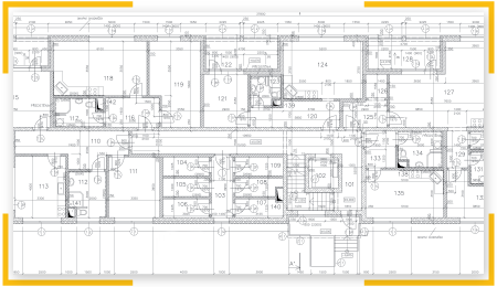
Building projects become more expensive when there are unplanned changes during construction, since materials and skilled labor are wasted with every change. Coordinated shop drawings are a very useful tool when planning construction, since equipment and components are modeled exactly how they will be installed. Location conflicts and installation issues become evident, and contractors can fix them before starting construction.
When building systems are designed by a professional engineering firm, clash detection and resolution are a normal part of the process. However, design engineers cannot guess how contractors and suppliers will install every component. Even if a building design has zero clashes and specification issues, conflicts may appear when contractors provide detailed information. Consider that most construction documents use LOD 350 (Level of Development), while shop drawings use LOD 400 to indicate fabrication and installation details.
Contractors, subcontractors and equipment suppliers use shop drawings to describe exactly how all building systems will be installed. This includes mechanical, electrical and plumbing installations (MEP), and even fire protection systems. Shop drawings must also include the fabrication details of any custom-made components that are used in the project.
- Coordinated shop drawings are obtained when all individual shop drawings are combined with the approved construction drawings.
- In other words, coordinated drawings are the result of combining construction specifications with fabrication and installation details.
- Since shop drawings add information that was not present in design documents, new clashes may emerge.
- For example, the building model completed during the design phase may show zero conflicts between electrical conduit and air ducts. However, when supporting and installation details of each system are added, new location conflicts may be created.
- Coordinated shop drawings also consider structural elements like columns and beams, and architectural elements like partitions and drop ceilings.
- Coordinated shop drawings are also known as composite drawings or coordination drawings.
There are many situations that cause clashes and specification conflicts between building system components. The most obvious example is when components have overlapping parts in the model, since this makes their installation impossible. However, there are also clashes where components interfere with no contact. For instance, if two pieces of equipment must have a minimum clearance for maintenance purposes, they cannot be placed close together.
Coordinated shop drawings can also be used to manage the project more effectively. Even when all clashes have been resolved, there can still be conflict:
- Subcontractors tend to work fast, to charge for their work earlier. However, work completed by one subcontractor ahead of schedule may block the installation of other building components.
- With coordinated shop drawings, subcontractors can understand how their work affects other trades. This helps avoid conflicts due to lack of information.
- Some projects have reserved spaces for future expansions, or for non-critical installations that can be designed later. Project managers must also ensure that these spaces are not used by subcontractors.
Coordinated shop drawings may take some time to complete. However, this is a small price for the time, materials and labor they can save. When clashes and specification conflicts reach the construction stage undetected, they require design modifications and expensive change orders.
Shop drawings are sometimes confused with submittals. While they two terms are closely related, they mean different things:
- Submittals are all the documents used to communicate exactly what will be installed. These include installation details and technical specifications.
- Shop drawings provide an exact visual representation of how building systems will be installed, and they are part of the submittals.
Shop drawings on their own cannot always communicate the full scope of an installation. For this reason, they are submitted with complementary documents. A shop drawing can also be defined as the contractor’s visual representation of the work shown in design documents.

The general contractor (GC) is responsible for presenting coordinated shop drawings before starting construction. In projects that use construction management at risk (CMAR), the responsibility falls on the construction management firm. From part of the owner, coordinated shop drawings must be approved by the project architect and design engineers. However, the main responsibility for these drawings falls on the general contractor or construction manager.
Coordinated shop drawings show installations from all trades - HVAC, electricity, plumbing, fire protection, communications. Therefore, these drawings require the input of all suppliers and subcontractors involved. They provide shop drawing for the scope of work, and the GC or CM integrates them into coordinated shop drawings.
When a general contractor or construction management firm presents the coordinated shop drawings, there is a high degree of responsibility involved. The project architect assumes that the contractor already completed all the following steps:
- All shop drawings from subcontractors and suppliers have been reviewed and approved by the GC or CMAR.
- The material quantities have been verified and approved.
- All field measurements have been verified and approved.
- The GC or CM approves the construction criteria used by suppliers and subcontractors.
- All the information and technical specifications provided along with shop drawings have been checked and approved.
- Coordinated shop drawings and other submittals meet all requirements in the project contract.
Coordinated shop drawings serve as proof that equipment and components from all trades can be installed without conflict. A complete set of coordinated shop drawings means that clashes and specification errors have been solved, and the project can move forward without hurdles.
The general contractor is responsible for presenting coordinated shop drawings correctly. However, the owner’s architects and design engineers can ask for clarifications, or make corrections if necessary.
There are also cases where the contractor must request necessary changes to make the installation possible. All changes of this type must be approved and signed by the project architect. The contract documents must then be updated to reflect any changes in the scope of work.
Contractors can also suggest changes that simplify the installation, even when they are not necessary. These changes must also be approved by the architect.
Prefabrication is a promising construction method, since most of the work is taken off-site, and completed in controlled factory conditions. Prefabricated modules are delivered to the project site to be assembled, and the building is completed in a fraction of the time needed by conventional methods. Most construction work is isolated from external factors like the weather and traffic, and the building process becomes less disruptive for neighbors.
However, prefabricated buildings bring a technical challenge: they must be designed as a set of modules with integrated MEP systems. Since each project is unique, these modules must be clearly specified to prevent fabrication errors. Coordinated shop drawings are very useful when arranging the mechanical, electrical, plumbing and fire protection systems in a prefabricated building.
By taking the time to develop coordination drawings for a prefabricated building, contractors can ensure that all modules are manufactured correctly. When these modules are delivered to the project site, they will fit together without issues.
A prefabricated building can be assembled virtually with coordinated shop drawings, before proceeding with actual fabrication and assembly. Modular construction is much faster, but the margin of error is also less compared with conventional construction.
- Change orders can be completed more easily when traditional construction methods are used.
- However, if part of a modular building is fabricated incorrectly, it must be sent back to the factory for the required changes. This can delay the construction process significantly, and major modifications have higher costs.
Coordinated shop drawings must include equipment and components from all trades in the same model. Completing this task with 2D CAD software is possible, but the amount of information can become overwhelming. Also, consider that components at different elevations are shown with overlap in a 2D drawing.
Building information modeling (BIM) software like Autodesk Revit is a much better option for coordinated shop drawings, since all components can be represented in three dimensions.
- This is especially useful when many components share small spaces, such as electrical and mechanical rooms.
- A three-dimensional model that represents the actual installation is much easier to understand than a 2D drawing with overlapping components.
- Conventional drawings are even more difficult to understand when they use PDF format, since they cannot be manipulated easily.
The limitations of 2D drawings are evident when drawing distribution systems that share spaces. Air ducts, electrical conduit and fire sprinkler piping above a dropped ceiling can be modeled more easily in three dimensions, for example. When these distribution systems are drawn in the same 2D sheet, the coordination drawing can become very confusing. In the modern construction industry, not using BIM software is a major competitive disadvantage.
Coordinated shop drawings must include dimensions, clearances and installation details for all components and equipment. However, the general requirements can be summarized as follows:
- Preventing any physical location conflicts between building components.
- Meeting all clearances required by building codes, design standards, and manufacturer specifications.
- Verifying all vertical elevations for routing (conduit, air ducts, piping, etc.)
- Equipment support dimensions and clash prevention.
- Wall and roof penetrations for ductwork, piping, conduit and cable trays.
- Leaving enough space for electrical panels and any components with openable covers.
- Coordinating all systems above the ceiling (lighting, conduit, air ducts, piping, etc.)
Using outsourcing for coordinated shop drawings is a viable strategy for general contractors. This way, contractors can focus on completing their projects on time, while drawings are delegated to a specialist engineering firm. When contractors lack experience with shop drawings, outsource allows a much faster completion without errors.
Preventing change orders and modifications in construction projects is beneficial for all parties involved. Depending on how the contract is written, additional costs may be assumed by the owner, the general contractor or both. However, someone will lose money in any case.
Change orders also delay the project, which can have a negative impact on the track record of engineering firms and contractors. Also, if the project developer plans to rent residential or commercial spaces, a later completion means waiting more to charge rent.
Coordinated Shop Drawings
Building projects become more expensive when there are unplanned changes during construction, since materials and skilled labor are wasted with every change. Coordinated shop drawings are a very useful tool when planning construction, since equipment and components are modeled exactly how they will be installed. Location conflicts and installation issues become evident, and contractors can fix them before starting construction.
When building systems are designed by a professional engineering firm, clash detection and resolution are a normal part of the process. However, design engineers cannot guess how contractors and suppliers will install every component. Even if a building design has zero clashes and specification issues, conflicts may appear when contractors provide detailed information. Consider that most construction documents use LOD 350 (Level of Development), while shop drawings use LOD 400 to indicate fabrication and installation details.
Using Coordinated Shop Drawings Effectively
Contractors, subcontractors and equipment suppliers use shop drawings to describe exactly how all building systems will be installed. This includes mechanical, electrical and plumbing installations (MEP), and even fire protection systems. Shop drawings must also include the fabrication details of any custom-made components that are used in the project.
- Coordinated shop drawings are obtained when all individual shop drawings are combined with the approved construction drawings.
- In other words, coordinated drawings are the result of combining construction specifications with fabrication and installation details.
- Since shop drawings add information that was not present in design documents, new clashes may emerge.
- For example, the building model completed during the design phase may show zero conflicts between electrical conduit and air ducts. However, when supporting and installation details of each system are added, new location conflicts may be created.
- Coordinated shop drawings also consider structural elements like columns and beams, and architectural elements like partitions and drop ceilings.
- Coordinated shop drawings are also known as composite drawings or coordination drawings.
There are many situations that cause clashes and specification conflicts between building system components. The most obvious example is when components have overlapping parts in the model, since this makes their installation impossible. However, there are also clashes where components interfere with no contact. For instance, if two pieces of equipment must have a minimum clearance for maintenance purposes, they cannot be placed close together.
Coordinated shop drawings can also be used to manage the project more effectively. Even when all clashes have been resolved, there can still be conflict:
- Subcontractors tend to work fast, to charge for their work earlier. However, work completed by one subcontractor ahead of schedule may block the installation of other building components.
- With coordinated shop drawings, subcontractors can understand how their work affects other trades. This helps avoid conflicts due to lack of information.
- Some projects have reserved spaces for future expansions, or for non-critical installations that can be designed later. Project managers must also ensure that these spaces are not used by subcontractors.
Coordinated shop drawings may take some time to complete. However, this is a small price for the time, materials and labor they can save. When clashes and specification conflicts reach the construction stage undetected, they require design modifications and expensive change orders.
What Is the Difference Between Shop Drawings and Submittals?
Shop drawings are sometimes confused with submittals. While they two terms are closely related, they mean different things:
- Submittals are all the documents used to communicate exactly what will be installed. These include installation details and technical specifications.
- Shop drawings provide an exact visual representation of how building systems will be installed, and they are part of the submittals.
Shop drawings on their own cannot always communicate the full scope of an installation. For this reason, they are submitted with complementary documents. A shop drawing can also be defined as the contractor’s visual representation of the work shown in design documents.
Who Is Responsible for Coordinated Shop Drawings?
The general contractor (GC) is responsible for presenting coordinated shop drawings before starting construction. In projects that use construction management at risk (CMAR), the responsibility falls on the construction management firm. From part of the owner, coordinated shop drawings must be approved by the project architect and design engineers. However, the main responsibility for these drawings falls on the general contractor or construction manager.
Coordinated shop drawings show installations from all trades - HVAC, electricity, plumbing, fire protection, communications. Therefore, these drawings require the input of all suppliers and subcontractors involved. They provide shop drawing for the scope of work, and the GC or CM integrates them into coordinated shop drawings.
When a general contractor or construction management firm presents the coordinated shop drawings, there is a high degree of responsibility involved. The project architect assumes that the contractor already completed all the following steps:
- All shop drawings from subcontractors and suppliers have been reviewed and approved by the GC or CMAR.
- The material quantities have been verified and approved.
- All field measurements have been verified and approved.
- The GC or CM approves the construction criteria used by suppliers and subcontractors.
- All the information and technical specifications provided along with shop drawings have been checked and approved.
- Coordinated shop drawings and other submittals meet all requirements in the project contract.
Coordinated shop drawings serve as proof that equipment and components from all trades can be installed without conflict. A complete set of coordinated shop drawings means that clashes and specification errors have been solved, and the project can move forward without hurdles.
The general contractor is responsible for presenting coordinated shop drawings correctly. However, the owner’s architects and design engineers can ask for clarifications, or make corrections if necessary.
There are also cases where the contractor must request necessary changes to make the installation possible. All changes of this type must be approved and signed by the project architect. The contract documents must then be updated to reflect any changes in the scope of work.
Contractors can also suggest changes that simplify the installation, even when they are not necessary. These changes must also be approved by the architect.
Using Coordinated Shop Drawings in Prefabricated Buildings
Prefabrication is a promising construction method, since most of the work is taken off-site, and completed in controlled factory conditions. Prefabricated modules are delivered to the project site to be assembled, and the building is completed in a fraction of the time needed by conventional methods. Most construction work is isolated from external factors like the weather and traffic, and the building process becomes less disruptive for neighbors.
However, prefabricated buildings bring a technical challenge: they must be designed as a set of modules with integrated MEP systems. Since each project is unique, these modules must be clearly specified to prevent fabrication errors. Coordinated shop drawings are very useful when arranging the mechanical, electrical, plumbing and fire protection systems in a prefabricated building.
By taking the time to develop coordination drawings for a prefabricated building, contractors can ensure that all modules are manufactured correctly. When these modules are delivered to the project site, they will fit together without issues.
A prefabricated building can be assembled virtually with coordinated shop drawings, before proceeding with actual fabrication and assembly. Modular construction is much faster, but the margin of error is also less compared with conventional construction.
- Change orders can be completed more easily when traditional construction methods are used.
- However, if part of a modular building is fabricated incorrectly, it must be sent back to the factory for the required changes. This can delay the construction process significantly, and major modifications have higher costs.
How BIM Software Simplifies Coordinated Shop Drawings
Coordinated shop drawings must include equipment and components from all trades in the same model. Completing this task with 2D CAD software is possible, but the amount of information can become overwhelming. Also, consider that components at different elevations are shown with overlap in a 2D drawing.
Building information modeling (BIM) software like Autodesk Revit is a much better option for coordinated shop drawings, since all components can be represented in three dimensions.
- This is especially useful when many components share small spaces, such as electrical and mechanical rooms.
- A three-dimensional model that represents the actual installation is much easier to understand than a 2D drawing with overlapping components.
- Conventional drawings are even more difficult to understand when they use PDF format, since they cannot be manipulated easily.
The limitations of 2D drawings are evident when drawing distribution systems that share spaces. Air ducts, electrical conduit and fire sprinkler piping above a dropped ceiling can be modeled more easily in three dimensions, for example. When these distribution systems are drawn in the same 2D sheet, the coordination drawing can become very confusing. In the modern construction industry, not using BIM software is a major competitive disadvantage.
General Checklist for Coordinated Shop Drawings
Coordinated shop drawings must include dimensions, clearances and installation details for all components and equipment. However, the general requirements can be summarized as follows:
- Preventing any physical location conflicts between building components.
- Meeting all clearances required by building codes, design standards, and manufacturer specifications.
- Verifying all vertical elevations for routing (conduit, air ducts, piping, etc.)
- Equipment support dimensions and clash prevention.
- Wall and roof penetrations for ductwork, piping, conduit and cable trays.
- Leaving enough space for electrical panels and any components with openable covers.
- Coordinating all systems above the ceiling (lighting, conduit, air ducts, piping, etc.)
Using outsourcing for coordinated shop drawings is a viable strategy for general contractors. This way, contractors can focus on completing their projects on time, while drawings are delegated to a specialist engineering firm. When contractors lack experience with shop drawings, outsource allows a much faster completion without errors.
Preventing change orders and modifications in construction projects is beneficial for all parties involved. Depending on how the contract is written, additional costs may be assumed by the owner, the general contractor or both. However, someone will lose money in any case.
Change orders also delay the project, which can have a negative impact on the track record of engineering firms and contractors. Also, if the project developer plans to rent residential or commercial spaces, a later completion means waiting more to charge rent.
