
It is general knowledge that electricity consumers must pay for the total amount of kilowatt-hours supplied by the electric utility company, as measured by the corresponding power meter. However, since no electric conductor is perfect and even the highest quality wiring has resistance, part of that electricity is lost between the power meter and the point of use.
What is Voltage Drop?
One of the basic principles of electrical engineering is Ohm’s law, which states that the voltage drop across a conductor or load is equivalent to the product of current and resistance (V = I x R). The electric current is determined by the load on a circuit, while resistance is determined by the physical properties of the conductor.
Get your Voltage Drop Calculation report from our team of experts in just 5 days.

The concept of voltage drop is used to describe the difference between the voltage supplied at the source and the voltage measured at the load. The factors that determine voltage drop are summarized in the following table:
| VOLTAGE DROP FACTORS | DESCRIPTION |
|---|---|
| A. Conductor material | Some materials are better electrical conductors than others. For example, copper is more conductive than aluminum. |
| B. Conductor diameter | A wider conductor has improved conductivity because there is more material to carry electric current |
| C. Conductor length | Longer conductors have a higher resistance because the current must travel a longer distance between the source and the load. |
| D. Conductor temperature | Temperature influences the conductivity of materials. Depending on the material and the actual temperature, conductivity may increase or decrease with further increases in temperature. |
| E. Current carried by the conductor | Current is directly proportional to voltage drop. If the current is doubled while resistance is kept the same, the voltage drop also doubles. |
| F. Connections in the circuit | A connection represents an interruption in the conductor material, and there is a contact resistance associated with it. Deficient connections are associated with an increased voltage drop. |
How to Calculate Voltage Drop
It is important to note that the voltage drop formula changes depending on the number of phases in the circuit (single-phase or three-phase). In the following equations, the variables used are:
- Z = Impedance of the conductor (ohms per 1,000 feet, or ohms / kft)
- I = Load current (amperes)
- L = Length (feet)
| TYPE OF INSTALLATION | VOLTAGE DROP FORMULA |
|
Single-phase system Three-phase system |
V Drop = 2 x Z x I x L / 1000 V Drop = 1.73 x Z x I X L / 1000 |
The formulas are divided by 1,000 because standard impedance values are provided for every 1,000 feet. This way, they are converted to ohms per foot. Chapter 9 of the NEC provides conductor properties, based on a 75°C temperature rating.
To demonstrate the procedure, assume a single-phase 120-V circuit carries a current of 22 A, where the conductor impedance is 1.29 ohms per 1,000 ft, and the circuit length is 50 ft. The voltage drop would be:
- Voltage drop = ( 2 x 1.29 ohm / kft x 22A x 50 ft ) / 1,000 = 2.84 V
- Percentage voltage drop = 2.84V / 120V = 0.0237 = 2.37%
If there is more than one conductor per phase, the calculation above must be divided by the number of conductors per phase, since resistance is reduced. For example, if there are two conductors per phase in the example above, resistance is reduced by half, and the voltage drop would be 1.42V (1.18%).
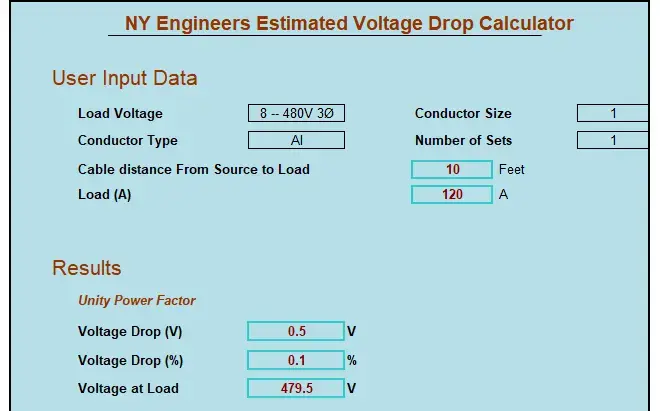

Select the material either copper or aluminum, the size of the conductor, the voltage and phase from a list of common voltages, then enter the one way circuit length in feet, and load in amperes. This program finds voltage drop, percent voltage drop, and volts at end of circuit.
How Can Voltage Drop Be Controlled?
Since there is no perfect conductor and all materials have electrical resistance, it is impossible to eliminate voltage drop completely. However, there are many ways to minimize it:
- Improving system efficiency
Assuming the load stays the same, increasing the efficiency of electrical equipment reduces power consumption. Since the supply voltage is constant, improved efficiency results in less current and a reduced voltage drop. - Troubleshooting
Some electrical issues cause an unnecessary increase in current or resistance, which leads to a higher voltage drop. Once these issues are solved, the voltage drop returns to normal. - Correcting conductor sizes
If the conductors in a circuit are not selected properly, they can experience a significant voltage drop. When selecting conductors, it is important to account for factors such as full-load current, ambient temperature, and the number of conductors in a raceway. - Centralized electrical distribution
If the main electrical shaft and distribution boards are located close to the center of a building, wiring must cross smaller distances to reach the different loads. This type of layout minimizes voltage drop. On the other hand, when the electrical shaft and panels are located at one end of the building, circuits must cross the entire construction to reach loads on the opposite side. - Balanced load distribution
Large commercial buildings typically use three-phase circuits, which have three live conductors as implied by their name. If one phase is too highly loaded, it will also experience a larger current and increased voltage drop compared with the other phases.
These are specific measures that can be deployed to reduce voltage drop. In general, any measure that accomplishes either of the following effects is viable, as long as it is allowed by the NYC Electrical Code:
- Decreasing load current
- Increasing conductor diameter
- Increasing the number of parallel conductors
- Decreasing conductor length
- Decreasing conductor temperature
Allowable Voltage Drop According to the NEC, 2011 Edition
The NFPA National Electric Code (NEC), which is the basis for the NYC Electrical Code, establishes two conditions for the allowable voltage drop in electrical installations:
- The maximum allowable voltage across a branch circuit is 3 percent, measured between the corresponding electrical panel and the farthest outlet delivering power, heating, lighting, or any combination of such loads.
- The maximum combined voltage drop across main feeders and branch circuits is 5 percent, measured from the service connection to the farthest power outlet.
These voltage drop levels are considered to provide reasonable operational efficiency. It is important to note that, when circuit conductors are increased in size to compensate for voltage drop, the equipment grounding conductor must be increased accordingly.
How to Select Wire Size?
The procedure explained above can be adjusted to select conductor size based on the allowable voltage drop. Assume a circuit is subject to the following conditions:
- Operating voltage = 120 V
- Configuration: Single-phase
- Current = 25 A
- Length = 100 ft
The voltage drop formula can be adjusted as follows, to calculate the required impedance.
- Voltage drop = 2 x Z x I x L / 1000
- Z = (1000 x Voltage Drop) / (2 x I x L)
Substituting the values above into the formula, the following result is obtained:
- Allowable voltage drop = 120V x 3% = 3.6V
- Z = (1000 x 3.6V) / (2 x 25A x 100ft) = 0.72 ohm / kft
According to the NEC in Chapter 9, Table 8, the required conductor size to keep voltage drop below 3% is AWG #6 (0.510 ohm / kft). The size that follows is AWG #8, but its resistance is too high (0.809 ohm / kft) and the voltage drop would exceed 3%.
Get a professional electrical design for your building, and avoid voltage issues.

Installation of Multiple Conductors in Conduit, Cable or Raceway
NEC Tables 310.16 through 310.19 provide the allowable ampacities for a maximum of three conductors in a conduit, cable or raceway. When the number of conductors is four or more, the allowable ampacity is reduced as shown in the following table:
|
NUMBER OF CURRENT-CARRYING CONDUCTORS |
PERCENT OF AMPACITY VALUE |
|
4-6 7-9 10-20 21-30 31-40 41 or more |
80% 70% 50% 45% 40% 35% |
Conductors must have an adequate ampacity for the load according to tables 310.16 through 310.19, while also having a voltage drop under the maximum allowable value of 3%. Also, note that rated ampacity is reduced when there are multiple conductors installed together. All three factors must be verified to have a code-compliant electrical installation.
Summary
The NEC recommends a maximum voltage drop of 5% across feeders and branch circuits, and 3% across the branch circuit alone. This voltage drop level is considered to offer the right conditions for optimal equipment performance. Note that the maximum allowable voltage drop level is not a safety measure, but a performance measure.
An electrical design makes your building safer, while reducing your power bills. NY Engineers has completed over 1000 projects, and you can email at info@ny-engineers.com or call.

