Ventilation Items and Joints

Vent piping must be designed to allow the air to flow freely, without unnecessary expansion or compression. When one considers that the plumbing system includes absolutely everything related to water supply and distribution as well as waste, the importance of vent piping design becomes apparent. NY Engineers offer a cost-effective plumbing design process that is quick and efficient, with vent piping receiving the same attention as all the other elements.

Need help?

Keith Fink

Principal

(786) 788-0295

inquiry@ny-engineers.com

Get In Touch

Why Choose Us?

We are one of the fastest growing MEP design firms in the construction industry. We pride ourselves on having a fast turnaround while providing cost effective solutions. We are licensed in 50 states and are your one stop shop for all MEP design needs.

0

States

We are licensed in all 50 states!

0

Errors

We design to the perfection

0

Days

Enjoy our lightening fast turnaround

0

Projects

We have completed so far!

0

First Time Approval

Our designs are approved by DOB in one go

0

Repeat Customers

The best service experience in the market

Get Pricing On a New MEP Design Proposal in Fewer than 24 Hours

Request a proposal

Design Of Plumbing Vent Piping

All plumbing systems must be designed with a system of vent piping that will allow air to be admitted or emitted without subjecting the seal of any fixture trap to a pneumatic pressure differential that is not more than 1 inch of water column (or 249 Pa or pascal). This pressure is also equivalent to a force of 1 newton acting over an area of 1 square meter.

Furthermore, every trap and fixture with a trap, that prevents the emission of sewer gases without affecting the flow of wastewater or sewage through the trap, must be vented in accordance with a venting method specified in the relevant local Code. These are specified in Chapter 9 Vents, in the New York City (NYC) Plumbing Code 2014.

Vent piping must be designed to allow the air to flow freely, without unnecessary expansion or compression.

When one considers that the plumbing system includes absolutely everything related to water supply and distribution as well as waste, the importance of vent piping design becomes apparent. More specifically, the plumbing system includes:

  • Water supply pipes
  • Water distribution pipes
  • Plumbing fixtures and traps
  • Equipment for both using and treating water
  • Vent, soil, and waste pipes
  • Building drains
  • Sanitary and storm sewers
  • All the connections, devices, and appurtenances within the building, structure, or premises used for the plumbing system

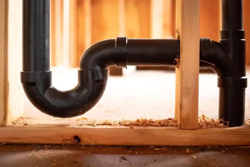
In effect, the vent piping system supplies fresh air and removes sewer gases and foul contaminated air that builds up in the plumbing system, and regulates the air pressure in the pipes. Together with the pipes that remove grey water and drains the remove sewage, the vent piping system forms a drain-waste-vent (DWV) system.

Vent Stacks And Stack Vents

Air ventilation Exterior Wall

Vent systems comprise pipes that are designed and installed so that they provide a flow of air to and from drainage systems, or circulation of air within drainage systems to protect trap seals from siphonage and backpressure.

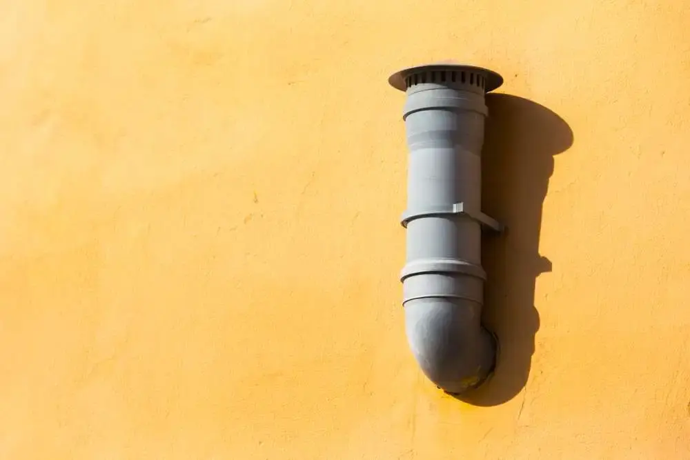
The NYC Plumbing Code 2014 requires that all buildings with plumbing installed have at least one four-inch (102 mm) vent stack or stack vent. This should be designed to run as directly as possible from the drain in the building, at the lowest part of the drainage system, through the roof to the air above.

Vent stacks are vertical vent pipes that are installed primarily to provide circulation of air between parts of the drainage system. These should connect either to the base of a drainage stack or to the building drain, and one is required for every drainage stack that is equal to three branch intervals or more. The latter is a vertical measurement of 8 feet (2438 mm) or more between the drainage stack and the connections of horizontal branches of the plumbing system.

Stack vents are the extensions of waste or soil stacks that extend above the highest horizontal drain that is connected to the stack. These should be designed as an extension of the drainage stack. The vent extension provides for the air that is dragged down the stack and supplies a means for the gravity circulation of air through the vent piping system. The vent stack also prevents excessive pressure from developing in the lower part of the drainage stack.

Design of Vents

Types Of Vents

Different types of vents are provided for fixtures and traps. They include:

  • Vents for fixture drains that run from a fixture to a junction point with any other drain pipe. Unless a vent for a fixture drain is installed for a fixture like a water closet (WC) that has an integral trap, it should connect above the weir of the trap that is being vented.
  • Individual vents may be provided for all traps and trapped fixtures but should not connect more than four feet to the fixture drain of the trapped fixture or trap being vented.
  • Common vents may be used to vent two trapped fixtures or traps. Essentially an individual vent shared by two traps, a common vent may only be connected to two traps or fixtures on the same floor level.
  • Horizontal wet vents are used for any bathroom fixtures except emergency floor drains. Wet vents extend from the connection of the dry vent along the direction of the flow in the drain pipe to the fixture drain connection that is most downstream on the horizontal branch drain. Wet vents should be at least 2 inches (51 mm) in size.
  • Circuit vents connect a horizontal drainage branch and vent two to eight traps or trapped fixtures. Where a circuit-vented horizontal branch receives the discharge from four or more WCs and connects to a drainage stack that receives the discharge of soil or waste from upper horizontal branches, a relief vent must be included in the vent piping design.
  • The importance of relief vents in multistory buildings cannot be underestimated and they should be located at various intervals throughout the drainage stack. They are also needed where a drainage stack is offset at an angle of more than 45 degrees to the vertical because of the high pneumatic pressure increases and extreme surging flow conditions they are subjected to.
  • Island fixture venting is only permitted for sinks and lavatories. It connects to the fixture drain in the same way as an individual or common vent and rises vertically to above the drainage outlet of the fixture that is being vented. Then it is offset either horizontally or vertically downwards. Vents and branch vents for multiple island fixture vents must extend to at least six inches (152 mm) above the highest fixture being vented before it is connected to the outside vent terminal.

Combination Vent And Drain Systems

The traps of floor drains and laboratory sinks may be vented with combination waste and vent piping systems. This is done in conjunction with a horizontal branch waste pipe that forms part of an independent waste system designed to carry flammable oil or acid.

Design specifications for combination systems are specified and the drain and vent pipe must have a no more than a one-half unit vertical in 12 units horizontal (4%) slope. The minimum slope depends on the size of the drainage pipe. If it is 2½ inches or less the minimum slope must be ¼ inch per one foot; 3-6 inch pipe requires 1/8 inch per foot; and if the drainage pipe is 8 inches or larger, the slope may be less – 1/16 inch per foot.

This kind of system requires either a dry vent connection or it may be connected to a horizontal drain that is vented in accordance with the NYC Plumbing Code.

Combination drain and vent systems that are connected to building drains that receive a discharge from stacks must incorporate a dry vent. Furthermore, the vent connection needs to extend at least 6 inches (152 mm) vertically above the flood level rim of the highest fixture being vented before it can be offset horizontally. This rim is, of course, the edge of the receptacle over which water can overflow.

The size of the combination drain and vent pipe used is directly related to the number of drainage fixture units (dfu) included in the design. The more dfu there are, the greater the diameter of the pipe will need to be. So, for example, if only three dfu are connected to a horizontal branch or stack, or four are connected to a building drain or sub-drain, the diameter of the pipe will be 2 inches (50.8 mm). If there are as many as 360 dfu connected to a branch or stack, or 575 to a building drain, 6 inch-diameter drain and vent pipe must be used.

Engineered And Computerized Vent Systems

More complicated engineered vent systems are sometimes necessary, particularly for larger buildings and industrial situations. Apart from anything else, the maximum length of a pipeline designed for individual fixture vents to vent branches and headers must conform to minimum pipe diameters at specific vent airflow rates.

Once the design is complete, a licensed professional engineer is required to inspect and certify the system.

The regulations allow computerized vent design provided the computer program design methods used are approved by the Commissioner of Buildings who ensures that these are compliant with the minimum standards of the Code.

Vent systems of computerized systems are based on the air capacity requirements of the relevant drainage system under peak load conditions. As with engineered systems, a licensed professional engineer is required to inspect and certify the completed system.

Our MEP engineers are fully equipped to design both engineered and computerized vent systems.

Pipes For Vents

Acceptable Materials For Vent Pipes And Flashings

Acceptable Materials For Vent Pipes And Flashings

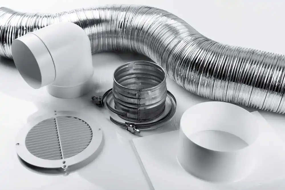
The materials that are acceptable for vent pipe correspond with those used for sanitary drainage, with differentiation between above-ground and below-ground pipes. Each type of pipe must conform to specified standards.

Above-ground vent pipes for residential buildings that are no more than five stories high may be made of several types of plastic:

  • Acrylonitrile butadiene styrene (ABS) plastic pipe in traditional iron pipe size (IPS) diameters, with a solid, cellular core or composite wall.
  • Polyolefin pipe.
  • Polyvinyl chloride (PVC) plastic pipe in IPS diameters with a solid, cellular core or composite wall.
  • PVC plastic pipe with a 3.25 inch outside diameter and a solid, cellular core or composite wall.
  • Polyvinylidene fluoride (PVDF) plastic pipe.

Glass pipe is also permitted along with various types of metal pipe made from brass, cast-iron, copper and copper-alloy pipe and types of tubing, ductile iron, galvanized steel pipe, high silicone case iron, and stainless steel drainage systems.

Underground vent pipes for residential buildings five stories or less in height may be made from PVC plastic pipe in IPS diameters with a solid, cellular core or composite wall.

Alternatively, cast-iron pipe, copper or copper-alloy tubing, ductile iron, non-asbestos fiber cement pipe, or stainless steel drainage systems may be used.

The Code also specifies acceptable materials for vent pipe flashings, which should be made of either sheet copper or sheet lead:

  • Sheet copper should weigh at least 8 ounces per square foot (2.5 kg/m2)
  • Sheet lead should weigh at least 3 lbs per square foot (15 kg/m2) if it is constructed on site and at least 2.5 lbs per square foot (12 kg/m2) if the flashings are prefabricated.

Vent Pipe Sizing

The sizing of all elements of vent piping design is governed by specifications and regulations. This includes the size of stack vents and vent stacks, individual, branch, circuit, and relief vents, as well as multiple branch and ejector vents.

The minimum diameter of vent stacks and stack vents is worked out from the “developed length” of the pipeline and the total number of drainage fixtures that are connected to them. There is also an important rule of thumb, which is that the diameter may never be less than half the diameter of the drain that the stack vent or vent stack is serving, or less than 1½ inches (38 mm) in diameter.

The Code provides an easy-to-read table to determine sizes. This shows the diameter of soil or waste stacks in inches, the total number of fixture units to be vented, and the maximum developed length of vent in feet (measured from the vent connection to the open air), and diameter of the vent in inches.

The developed length of any individual, branch, circuit, or relief vent is measured from the farthest point of the vent connection to the drainage system, to the point that it connects to the stock vent or vent stack or termination outside of the building.

The diameter of individual and other vents needs to be at least half the required diameter of the drain served, but vent pipes must be at least 1½ inches (38 mm) in diameter. Vents are sized in accordance with the table mentioned above unless there are more than 10 branch intervals, in which case a similar but different table is used.

There are also tables to determine the size of ejector vents including sewage pumps that may or may not be pneumatic. Those that are not pneumatic operate at atmospheric pressure and receive drainage discharge under gravity flow conditions.

Have an MEP Engineering Project? Talk To Us.