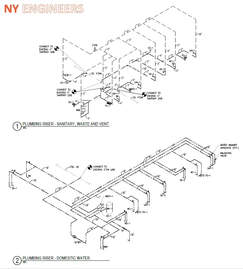
The point of a plumbing riser diagram is to separate out plumbing systems for potable water, waste water, storm water, sewage, and so on to be able to identify exactly where the different piping is located and what it is attached to in terms of appliances, drains, other building systems, and so on. There is, of course, a lot more to plumbing engineering than we have mentioned here. Nearby Engineers has a trained team of professionals to work on the full range of projects. Call for a consultation to see how we can help you.

First of all, it is important to understand what risers are. In essence, they are pipes, but very specific pipes.
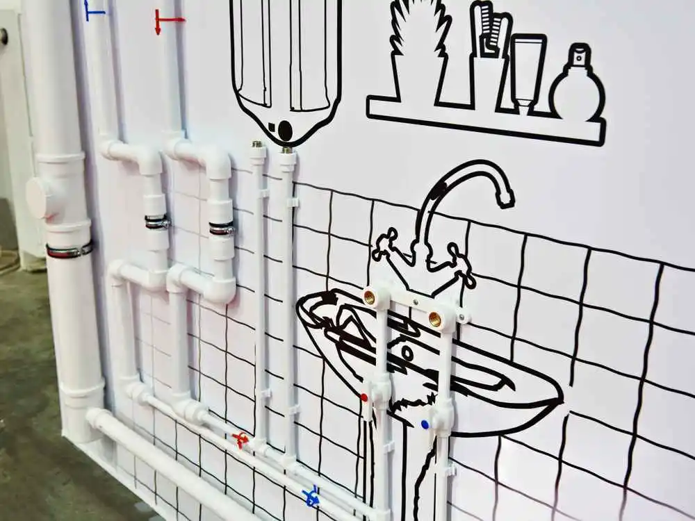
In the given picture, you can see a large waste pipe, and the cold and hot water supply pipes (marked blue and red respectively) leading to the position of the sink, indicated by a line drawing. The position of all of these, and all other relevant piping, will be shown on a riser diagram. However, only the water supply pipe is actually a riser.
The New York City (NYC) Plumbing Code defines risers as water pipes that extend one full story or more and convey water to a group of fixtures (like baths, sinks, showers, and lavatories) or to branches that extend to fixtures on two or fewer consecutive floors. Branches do not include risers, mains water pipes, or stacks, the latter of which are vertical lines of soil (for sewage), waste (water from fixtures and appliances, commonly called gray water), vents (to get rid of harmful gases), or inside conductor piping (for storm water).
However, it isn’t only risers that are included in plumbing riser diagrams, as you can see in Design of Plumbing Systems below. For instance, the NYC Department of Building (DOB) requires stacks to be shown on plumbing riser diagrams even though they are not risers! So too does the NYC Plumbing Code.
The point of a plumbing riser diagram is to separate out plumbing systems for potable water, waste water, storm water, sewage, and so on to be able to identify exactly where the different piping is located and what it is attached to in terms of appliances, drains, other building systems, and so on.
A plumber riser diagram is not necessarily drawn to scale, but it must be accurate enough to clearly show the concept. It is often created as a 2D diagram rather than an isometric 3D or an even more complicated axiomatic drawing.
What it needs to show is how the risers and various other pipes relate to one another and to fixtures, drains, traps, and valves or taps, but with just a series of lines. Water and waste pipes are shown as solid lines while vents are shown as dotted lines.
The NYC DOB has guidelines for the “design professional requirements” for plumbing projects in the city. First and foremost, it is essential for a state-licensed engineer, such as the highly experienced engineers who work for , or architect to submit work permit applications and the plans required for the project to the DOB. For all plumbing installation and modification projects, engineers and architects are encouraged to submit project applications that have been professionally certified to show that they have been completed in accordance with the relevant codes and other legislation.
From July 2019, all permit requests and plumbing job filings have to be submitted via DOB NOW, a new online tool that has been introduced to simplify business dealing with the DOB. Even though the DOB already has an eFiling system in place, from July 2019, no paper filings will be accepted.
The NYC DOB provides useful information that will help all non-professionals understand the wide range of construction documents required for both new builds and alterations/modifications. Riser diagrams are, of course, mentioned along with the usual site and floor plans, as well as detail drawings, and an energy analysis. Essentially, if any new piping is to be installed a riser diagram is required to show the details for:
Elevations across floors must also be indicated.
In terms of the codes that legislate plumbing design (including plumbing riser diagrams), while the NYC Building Code has a chapter on plumbing systems, all this states is that the NYC Plumbing Code governs the “construction, erection, installation, alteration, repairs, relocation, replacement, addition to, use or maintenance of plumbing equipment and systems.”
So, it is the Plumbing Code that we, as MEP engineers, refer to for mandatory requirements for construction documents of various kinds required for building permits. The Code requires very specific data and information from construction plans and you will see that the plumbing riser diagram is only one of the five listed below:
Of course, the Plumbing Code also has comprehensive details relating to the design of building water distribution systems, sanitary drainage, storm drainage, and vents, all of which are relevant to plumbing riser diagrams.
Note that while fire sprinklers off domestic, standpipe, and gas supply piping are mentioned in the DOB guidelines, they are not regulated by the NYC Plumbing Code but rather by the NYC Fire Code and the NYC Building Code. However, the specifications are that sprinkler systems should be designed and installed in accordance with National Fire Protection Association (NFPA) standards, particularly:
Even though plumbing riser diagrams for buildings can incorporate water supply and waste water, storm water, and sewage, plumbing systems in large, high-rise buildings are complex and so these two broad elements are quite often separated into two riser diagrams. If there is a sprinkler system, this may also be shown in a separate riser diagram. For this reason, we will discuss the different elements separately.
Riser diagrams for water supply show both the hot and cold water lines. Their layout and specification is simpler than waste pipes and designers have more freedom because the pipes are under pressure. Generally, water supply pipes can go anywhere because they are not linked to drains and vents.
Of course, the design of the building water distribution system will determine the layout of the plumbing riser diagram, whether or not waste water, and so in, is included in the diagram.
Both the flow rate and the flow pressure are important criteria for water distribution systems and pipe sizes need to be selected in keeping with conditions of peak demand.
The minimum size of fixture supply pipe varies according to the fixture it is supplying water to. So, for instance, 3/8 inch pipe is adequate for lavatories, some water closets, lavatories, bidets, and drinking fountains, but ½ inch pipe is more usual and required for bathtubs, domestic dishwashers, kitchen sinks, single-head showers, and wall hydrants. Flush-valve water closets require a bigger 1-inch pipe. Each fixture supply pipe requires a stop valve of the required type. The supply pipe must also extend to the floor or to a wall adjacent to the fixture that is supplied with hot or cold water. Sometimes water-pressure reducing valves or regulators are required.
Another important aspect of water supply is that potable (drinkable) water must not be contaminated in the system. This means that it is essential to ensure that non-potable liquids, solids, or gases cannot escape into the water supply piping. Various backflow preventers are mandatory. They include:
Additionally, supply lines and fittings for plumbing fixtures must be installed so that there is no chance of backflow.
We have already said that stacks include sanitary, storm, and vent piping.
Sanitary piping conveys sewage. Storm piping conveys storm water, groundwater and potable clear water waste from fixtures and appliances. It doesn’t contain any sewage or fecal matter. However, we sometimes use waste pipes that only convey waste water.
Vent pipes are part of a vent system that incorporates pipes that are designed and installed to provide airflow to or from drainage systems. They are often designed to protect trap seals, fitted to prevent the emission of sewer gases, from backpressure and siphonage.
Other terminology relating to stacks and vent piping includes reference to:
Like water supply pipes, the pipes used for sanitary or soil, waste, and vent pipe are governed by the NYC Plumbing Code and the standards specified in the Code. Generally, the pipes are a lot bigger than the pipes used for water supply. For instance, WC pipes are usually 3.5 to 4 inches.
We have already discussed the need to separate water supply pipes from the drainage system. Piping used for supply and drainage run parallel but they must never touch because of the dangers and risks of contamination.
While air gaps or valves may be used, air gaps are more common. In a drainage system, an air gap is defined as the unobstructed vertical distance “through the free atmosphere” between a waste pipe outlet and the flood level rim of the receptacle into which the waste pipe discharges.
All these pipes must be shown on the plumbing riser diagram.
Fire sprinklers are now mandatory for all business buildings that are 100 feet or taller. This includes high-rise office buildings.
While the NFPA standards cover the design and installation of sprinkler systems, if these are included in any plumbing system, they need to be included in a plumbing riser diagram.
Also, if non-potable water is installed in a building for the use of fire sprinklers, piping must be identified with metal tags or with a color. For instance, purple is used to identify rain, recycled, and gray water distribution systems. In New York, outlets that discharge non-potable water must also be identified, specifically with the words: “Caution. Nonpotable Water. Do Not Drink.”
There is, of course, a lot more to plumbing engineering than we have mentioned here. has a trained team of professionals to work on the full range of projects. Call for a consultation to see how we can help you.